42
Wall Fire Stop Installation
1. Cut an opening in the wall that is a minimum of 2” and maximum of 3” larger than the outside diameter
of the duct being installed, refer to Table 8.
2. The grease duct can be installed eccentrically or concentrically within the opening. The distance from
the outside of the grease duct to the periphery of the opening cannot exceed 2”. The maximum annular
distance allowed is 2”, refer to Figure 26.
3. Apply a continuous 1/2” bead of STI Triple S intumescent around the fire plates. The fire plates are
designed to fit around the duct and overlap by 1”.
4. The fire plates are installed on the backside of the wall. Push the plates up to the wall so the
intumescent seals the plates against the wall. Then secure using 1/4”-20 x 1-1/2” long concrete
fasteners where the plates overlap, secure using 1/4”-20 x 1” sheet metal screws.
5. Apply a 3/4” covering of intumescent sealant to the inside of the fire plates installed on backside of the
wall. The sealant should be smooth and without any gaps on the edges of the opening or outside of
duct.
6. Fill the cavity using the insulation provided, ensuring that all voids are filled. The insulation is fully
compressed into the opening until it is 3/4” from the edge of the opening in the wall.
7. Cover the compressed insulation with intumescent. Continue until the intumescent is flush with the
edge of the wall opening. The intumescent should overlap on to the wall, ensuring there are no gaps
between the edges of the opening or the duct outer shell.
8. Install the fire plates on the front side of the wall. Push the plates up to the wall so the intumescent
seals the plates against the wall. Then secure using 1/4”-20 x 1-1/2” long concrete fasteners where the
plates overlap secure using 1/4”-20 x 1” sheet metal screws.
9. Wrap one layer of 1” x 12” provided insulation around the base of the duct and enclose with the half
enclosure bands. The insulation and bands should be touching the intumescent. The enclosure bands
are assembled using 1/4”-20 x 1" hardware. This is done on the front and back of the wall.
10. Horizontal supports are used to support the duct on either side of the wall. Refer to Figure 15 for
details.
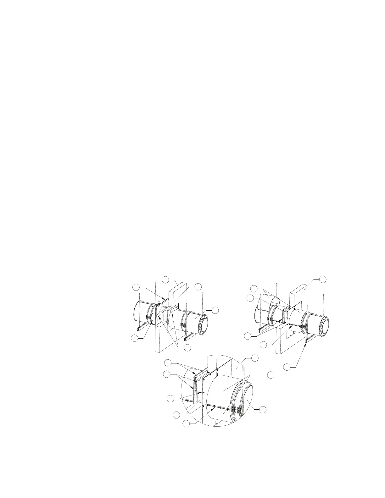
Figure 30 - Wall Fire Stop Installation
1. Fire Plates
2. Wall
3. Insulation
4. Duct Section
5. Intumescent
6. Concrete Screws
7. Half Closure Bands
8. Horizontal Support
9. 1/4”-20 Hardware