46
Chimney Assembly
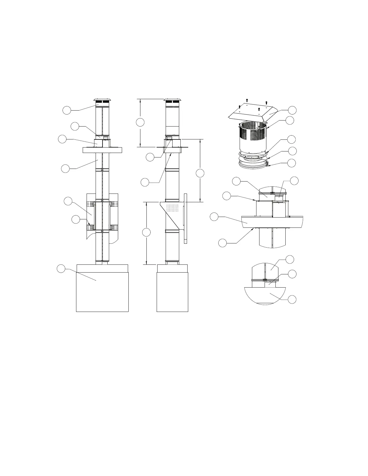
The illustrations shown provide useful information on the installation of a chimney system. Each installation
is specific to the application and the job site. If you encounter a situation not covered by this illustration,
refer to the guide or consult the factory. The chimney systems illustrated in this manual have been tested
to and comply with UL 103 Type HT, Factory-Built Chimneys for Building Heating Appliances. Chimney
needs to be installed additionally in accordance with NFPA 211.
Figure 34 - Chimney Installation Guide Details View 1
1. Vent Cap
2. Top Riser Cover and V-band
3. Vented Curb
4. Chimney Shell
5. Wall
6. Vertical Wall Support
7. Appliance
8. Top Riser Connection
9. Clearance Plate
10. Cap
11. Airshaft
12. Flange Ring
13. End Cap
14. Single V-band
15. Transition Plate
16. Substrate Surface
17. Connection to Appliance - May be welded/
bolted or field installed
A. Roof support assembly without support -
Maximum Distance is 8’
B. Vertical Support Spacing, refer to Table 6
1
2
3
4
5
6
7
A
B
B
8
9
10
11
12
13
14
8
2
15
16
9
4
17
7