45
The illustrations shown provide useful information on the installation of grease duct systems. Each
installation is specific to the application and the job site. If you encounter a situation not covered by this
illustration, refer to the guide or consult the factory. The grease duct systems illustrated in this manual
have been tested to and comply with UL 2221, Tests of Fire Resistive Grease Duct Enclosure Assemblies.
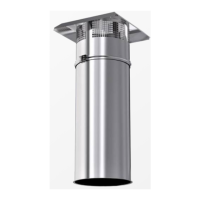
Adjustable duct and standard ducts are used to terminate at the transition plate. The duct section is fully
welded to the transition plate at the factory.
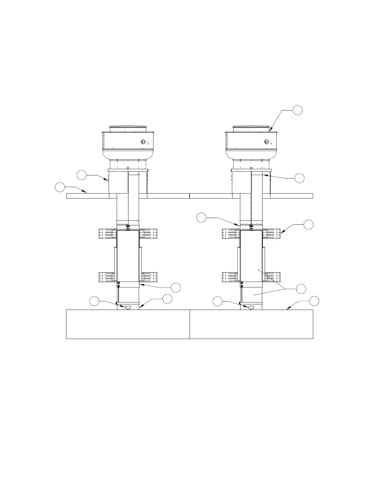
Figure 33 - Grease Duct Installation Guide Details View 3
1. Exhaust Fan
2. Adjustable Section - Terminates at transition
plate.
3. Vertical Support - Installed under V-band.
4. Standard Duct Length
5. Exhaust Hood
6. Duct Sensor
7. Riser Cover
8. Double V-band
9. Roof
10. Vented Curb