47
The illustrations shown provide useful information on the installation of a chimney system. Each installation
is specific to the application and the job site. If you encounter a situation not covered by this illustration,
refer to the guide or consult the factory. The chimney systems illustrated in this manual have been tested
to and comply with UL 103 Type HT, Factory-Built Chimneys for Building Heating Appliances. Chimney
needs to be installed additionally in accordance with NFPA 211.
There is no limit on the angle or slope of an offset for gas or liquid fuel burning appliances, but with a solid
fuel burning appliance the slope must not be greater than 30 degrees (USA) or 45 degrees (Canada) from
vertical.
Chimney for combination fuel heating appliances which are capable of burning solid fuel or are convertible
to solid fuel are limited to the same 30 degrees (US) or 45 degrees (Canada) slope even if the current
choice of fuel is gas or oil.
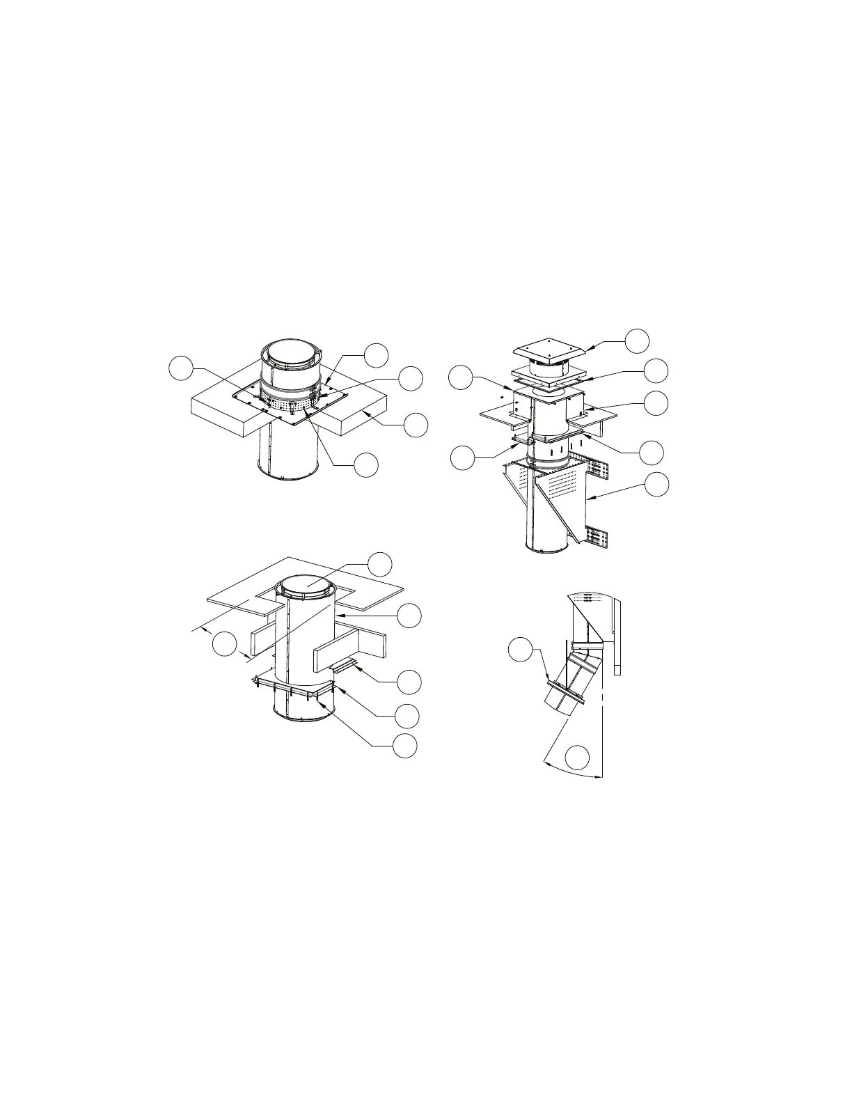
Figure 35 - Chimney Installation Guide Details View 2
1. Vertical Support Plate
2. Vertical Support Ring
3. Substrate
4. 5/16”-18 x 1-1/2” Self Drilling Screws
5. 1/4”-20 Whiz Nuts and Bolts
6. Base Cap
7. Ceramic Gasket
8. Vented Curb
9. Clearance Plate 1
10. Vertical Support
11. Clearance Plate 2
12. Transition Plate
13. Inside Shell
14. Chimney Shell
15. Clearance Plate Hardware
16. Vertical Floor Support with Threaded Rod
A. Floor Opening, refer to Table 9
B. Maximum angle not to exceed when being
used with solid fuel chimney applications - 30°
USA (45°Canada)
BASE MOUNT CAP.
VERTICAL FLOOR SUPPORT.
1
2
3
5
4
6
7
8
10
11
12
13
14
9
9
11
15
A
16
B
For Solid Fuel Appliances