EasyManua.ls Logo

CaptiveAire DW - Page 31

CaptiveAire DW
52 pages
Print Icon
To Next Page IconTo Next Page
To Previous Page IconTo Previous Page
Loading...
31
Figure 20 - Vertical Support (Concrete)
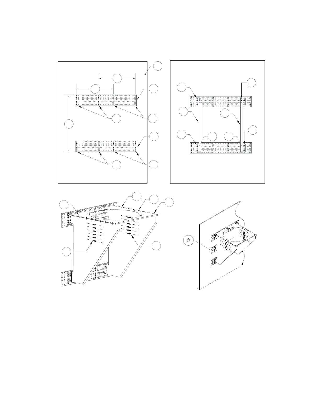
1. Wall Substrate (Concrete)
2. Wall Support Plate #1
3. Hardware from Mounting Kit for Concrete -
5/16” x 2-1/4” Concrete/Masonry Screws and
Washers
4. Wall Support Plate #2
5. Side Support Plate #1
6. Side Support Plate #2
7. Rear Flat Support Plate
8. 5/16”-18 Hardware, secures flat plates to the
side plates.
9. Front Flat Support Plate
10. 5/16”-18 x 1-1/2” Self-Drilling Screws
A. 44” Spacing Distance
B. 24” Centered Spacing Distance
DETAIL A DETAIL B
DETAIL C
2
1
A
3
3
3
3
3
3
5
6
7
9
10
8
8
10
B
B
3
3
3
4
3
30”/36” Additional Support Shown
*
* Third wall support plate used for 30”/36” duct.

Related product manuals