13
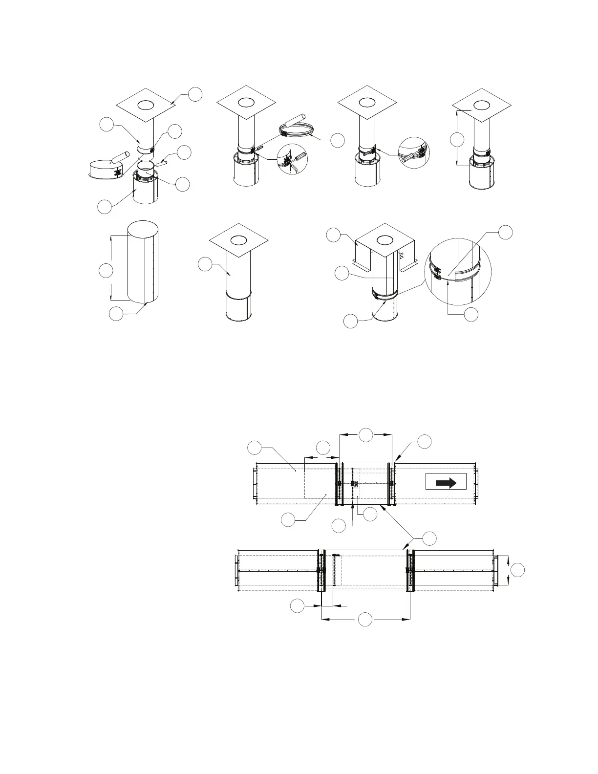
Figure 4 - Adjustable Duct, Chimney and Transition Plate
Figure 5 - Adjustable Duct and Chimney Overlap
NOTE: Protruding section may need to be cut in the field if there is interference with mating parts
in the duct run.
NOTE: When installing duct, verify directional label is in the correct direction of airflow.
(Exception: When grease is draining in a downward slope, the arrow should be opposite of airflow).
1. Transition Plate
2. Adjustable Collar
3. 3M Fire Barrier 2000 Plus
4. 7” Standard Duct Section
5. Mating Duct Section
6. Adjustable Duct Section
7. Single V-band
8. Outer Shell Cover
9. Insulation
10. Curb
11. Sheet Metal Screws
12. Double Wall V-band
13. Shell Overlap
14. Mating Duct Flange
X. Measured Distance
1. Duct Section
2. Double Wall V-band
3. Outer Shell Cover - Cut to size
4. Adjustable Collar
5. Single V-band
6. Adjustable Duct Section
A. Adjustable Section Protrusion -
May need to be cut
B. Minimum Length
C. Diameter
D. Maximum Length
E. Minimum Overlap
D
E
C
2
5
6
3
B
A1
FLOW DIRECTION
4