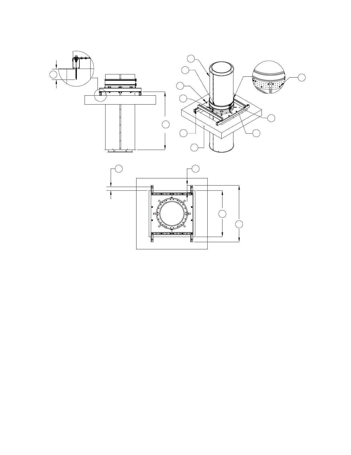
1. Double Wall Shell
2. Double Wall V-band
3. 3/8” Hardware
4. Floor Support Fastener Band
5. Substrate Fastener - Supplied by others
6. Substrate
7. B12 Unistrut
8. Floor Support
9. 5/16”-18 x 1-1/2” Self-Drilling Screws (Use
minimum 3 screws per opening in the band)
A. Minimum Thread Penetration, refer to
Table 7
B. Vertical Support Spacing, refer to Table 6
C. Minimum Edge Distance, refer to Table 7
D. 5” Maximum Distance
E. Open Area Chase
F. 48” Maximum Distance