8200-0753-0M Rev A 225D Weight Digital Indicator
6. Next, remove approximately 1 1/2 inches of the inner insulating jacket, exposing the
internal wires.
7. Now, remove 1/4 inch of insulation from the end of each of the five wires.
8. Make sure the inner insulating jacket extends past the outer braided jacket approximately
3/4 inch.
9. Referring to the table below (or on the circuit board) for terminal connections, connect each
wire to terminal block P5.
Terminal Block P5
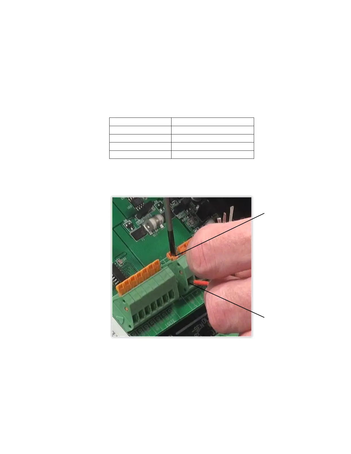
10. To terminate a wire, use a small flat blade screwdriver, and press down on the release bar
for the terminal. Insert the wire into the opening, and remove the screwdriver. The release
bar will return to its original position, locking the wire in place.
11. Repeat the procedure until all five wires are in place.
12. After all terminations have been made, remove the excess cable from the enclosure.
13. Insert the plastic insert into the gland connector.
14. Using a wrench, tighten the connector to make certain it is secure.