8200-0753-0M Rev A 225D Weight Digital Indicator
SETUP AND CONFIGURATION
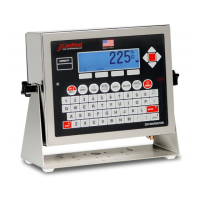
All digital scales are connected together with a daisy-chained CAN cable. The load cell
connection loop can begin at any convenient load cell, and may continue clockwise as shown
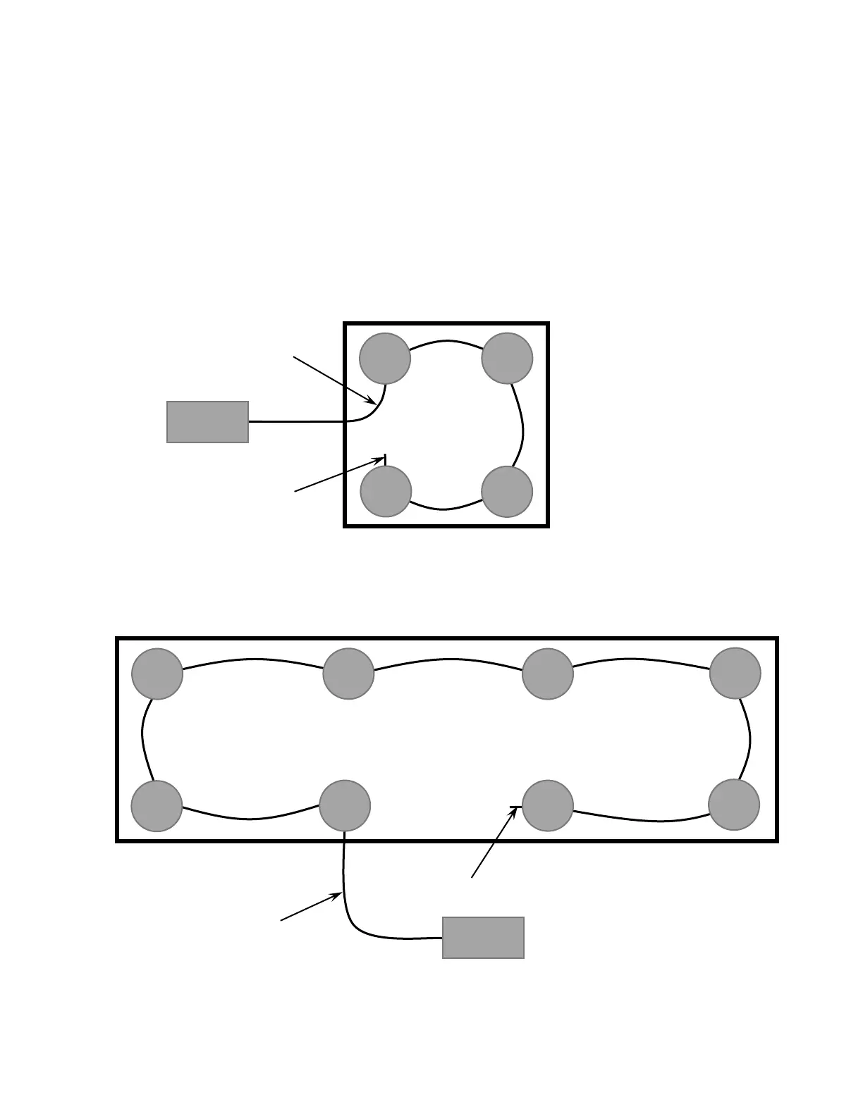
or counter-clockwise, if preferred. Note that in the tank/hopper example below there is not a
connection between cells 3 and 4 and in the truck scale example, there is not a connection
between cells 4 and 6.
NOTE: Be sure to insert the end node termination plug on the load cell at end of loop as
shown in both examples.
Example: Typical Tank/Hopper Configuration
NOTE: If the loop were run in the other direction, the sequence would then be 2-4-3-1 with
load cell 1 having the End Node Terminator installed on it.
Example: Typical Truck Scale Configuration
NOTE: If the loop were run in the other direction, the sequence would then be 6-8-7-5-3-1-2-4
with load cell 4 having the End Node Terminator installed on it.