EasyManuals Logo

Carel SD User Manual

Carel SD
52 pages
To Next Page IconTo Next Page
To Previous Page IconTo Previous Page
Page #13 background imageLoading...
Page #13 background image
9
Schemi elettrici
Alimentazione monofase (SD 101-102-103-106)
Wiring
Single-phase power supply (SD 101-102-103-106)
;;
;;
;;
;;
;;
;;
;;
61 62 54 55 67 66
65 63 64
52 53
50 51
68 69 56 57 58 59 60 70 71 72
20 21
External signal Alarm
Remote On/Off
= Primary voltage
B = 200 - 208V~
C = 220 - 240V~
D = 380 - 415V~
E = 440 - 480V~
F = 575V~
***
Line
K
Drain valve Fill valve
F2 1A ATM/gG
F3 1A ATM/gG
F1 1A ATM/gG
230V
0V
***
24V
0V
F4 2A GT
Transformer 100VA
ON/OFF
X1
X2
TAM
Level sensor
Control CDC / P / H / D / T
G G0
+12 S1 S2 GND -12 N0 C NC
56 57 58 59 60 70 71 72
Optional fan
K
Conductimeter
N L PE
Boiler
Mounted on
transformer
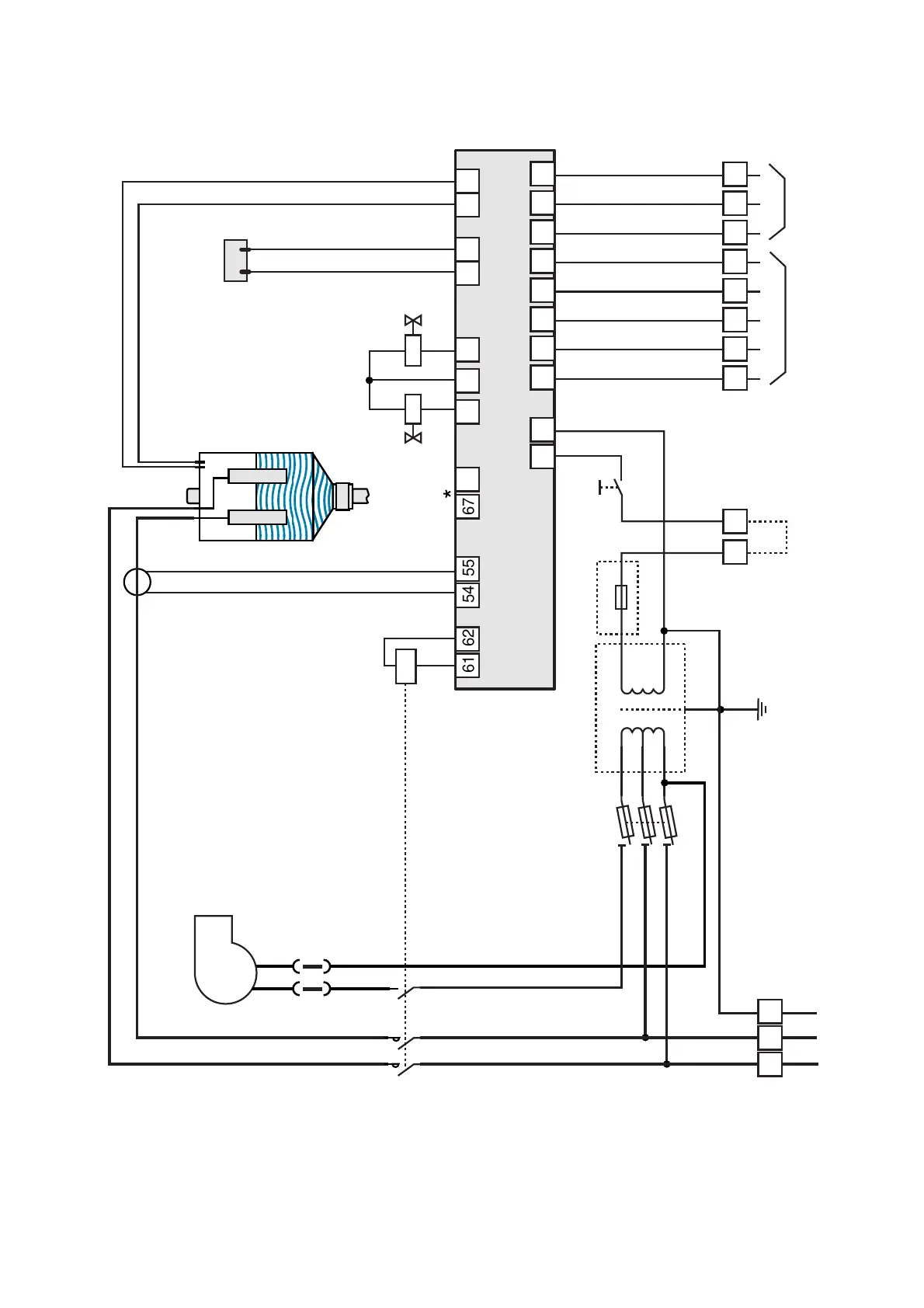
* I morsetti 66-67 sono presenti solo sul controllo in versione CDD per gestire la deumidificazione (vedi pag. 20). Il controllo
CDD può essere abbinato al controllo Macrobase per la gestione dell'umidificazione e deumidificazione di centrali
di trattamento aria. Caratteristiche uscita 66-67: I max 5 mA, V max 30 V~
The connections 66-67 are present only on the CDD controller for the dehumidifier management (see on page 20). The
CDD controller can be coupled with the Macrobase controller for the humidification/dehumidification management of air
handling units. Output 66-67 characteristics: Imax 5mA; Vmax 30V~
See page 24-25

Table of Contents

Other manuals for Carel SD

Questions and Answers:

Question and Answer IconNeed help?

Do you have a question about the Carel SD and is the answer not in the manual?

Carel SD Specifications

General IconGeneral
BrandCarel
ModelSD
CategoryHumidifier
LanguageEnglish

Related product manuals