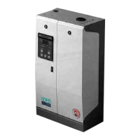
4.2 Posizione delle uscite tubi mandata vapore
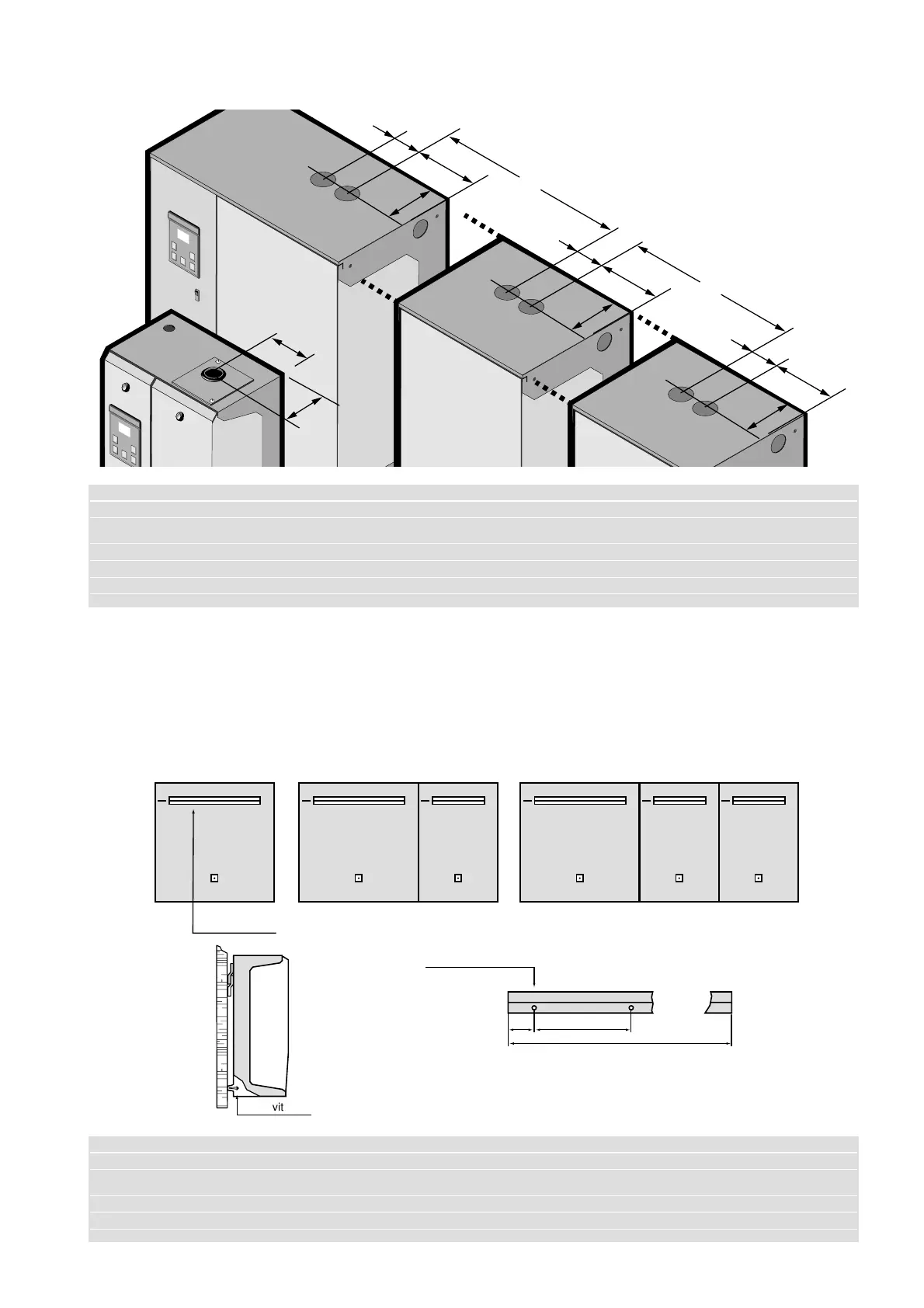
4.3 Montaggio a parete dell’umidificatore a vapore
È compresa a corredo dell’umidificatore una staffa a “L” da
fissare alla parete tramite delle viti. Una volta montata la
staffa a parete appendere l’umidificatore, fissandolo con le
viti di bloccaggio poste sullo schienale interno della parte
idraulica (vedi figura sottostante).
4.2 Position of steam outlets
4.3 Wall mounting of the steam humidifier
As a kit of the humidifier an “L” shaped bracket is supplied
to be attached to the wall by means of screws. Once the
bracket has been mounted on the wall, hang the humidifier and
secure it with the fixing screws that is placed in the internal
back-piece of the hydraulic part below (see figure below).
5
Modello SD 101-102-103-303-305 106-308-313 323-333-342 360-384 3B3
SD Model
A (mm) 80 80 80
B (mm) 81 105 170 170 170
C (mm) 310 310
D (mm) 95 110 145 145 145
Modello SD 101-102-103-303-305 106-308-313 323-333-342 360-384 3B3
SD Model
A (mm) 50 50 65 105 70
B (mm) 110 110 150 150 150
C (mm) 210 210 430 810 1190