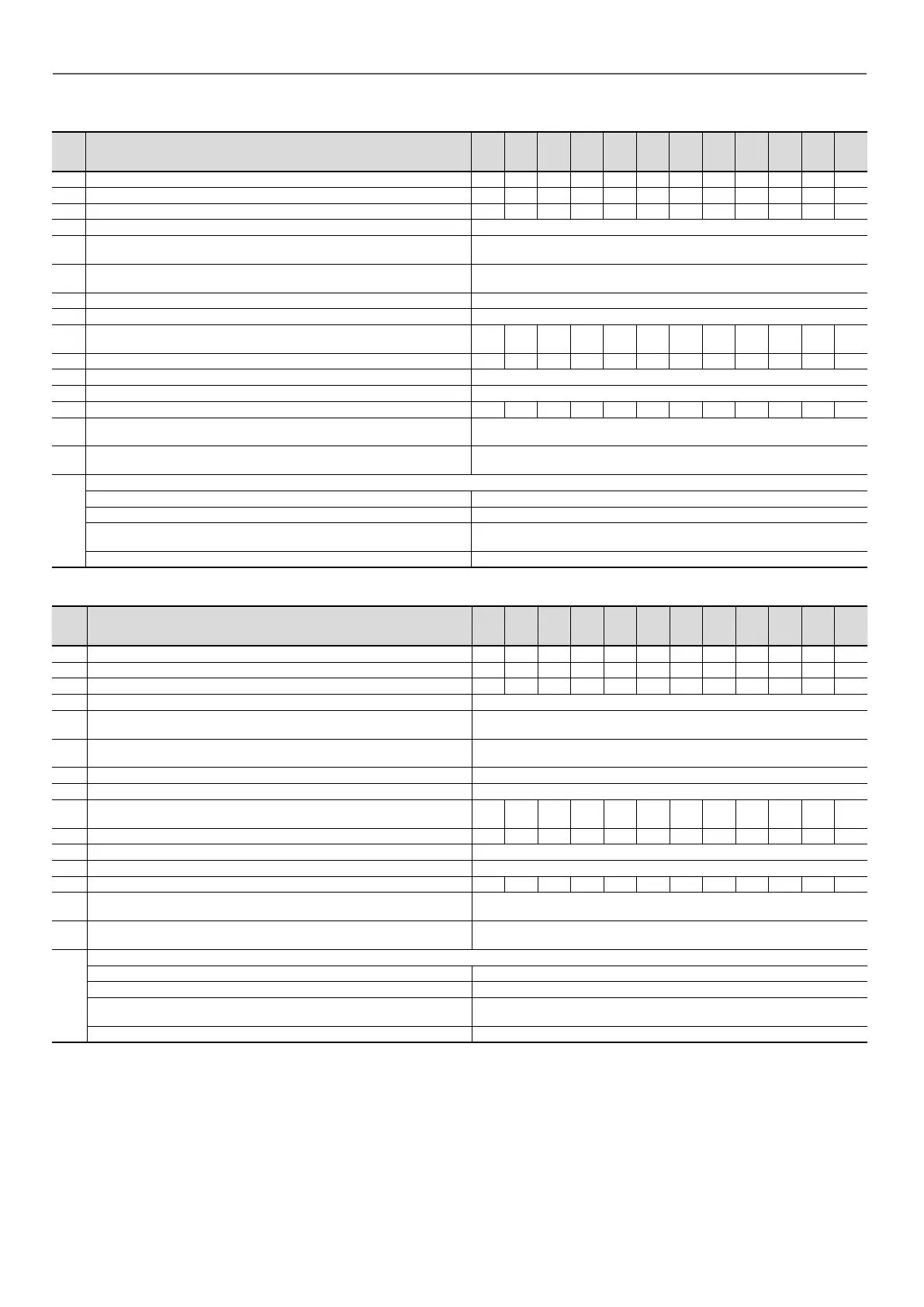
For the high pressure single pump motors of 30RQ/RQP 165-520R units (options 116R, 116V)
No.
(2)
Description
(3)
165R 180R 210R 230R 270R 310R 330R 370R 400R 430R 470R 520R
1 Nominal eciency at full load and nominal voltage % 87,5 87,5 89,6 89,6 89,6 89,7 89,7 89,7 89,7 90,8 90,8 90,8
1 Nominal eciency at 75% of full load and nominal voltage % 88,2 88,2 90,4 90,4 90,4 90 90 90 90 90,8 90,8 90,8
1 Nominal eciency at 50% of full load and nominal voltage % 87,5 87,5 89,9 89,9 89,9 89 89 89 89 89,6 89,6 89,6
2 Eciency level - IE3
3 Year of manufacture -
This information varies depending on the manufacturer and model at
the time of incorporation. Please refer to the motor name plates,
4
Manufacturer's name and trademark, commercial registration
number and head oce of manufacturer
- Same as above
5 Product model number - Same as above
6 Number of motor poles - 2
7-1
Nominal shaft power output at full load and nominal voltage
(400 V)
kW 3 3 4 4 4 5,5 5,5 5,5 5,5 7,5 7,5 7,5
7-2 Maximum input power (400 V)
(4)
kW 3,44 3,44 4,49 4,49 4,49 6,17 6,17 6,17 6,17 8,32 8,32 8,32
8 Nominal input frequency Hz 50
9-1 Nominal voltage V 3 x 400
9-2 Maximum current drawn (400 V)
(5)
A 6,33 6,33 7,75 7,75 7,75 10,40 10,40 10,40 10,40 14,10 14,10 14,10
10 Nominal speed
r/s -
rpm
48 - 2900
11 Product disassembly, recycling or disposal at end of life -
Disassembly using standard tools. Disposal and recycling using an
appropriate company
12
Operating conditions for which the motor is specically designed
I - Altitudes above sea level m < 1000
(6)
II - Ambient air temperature °C < 40
III - Maximum operating temperature °C
Please refer to the operating conditions given in this manual or in the
specic conditions given in the selection programs.
IV - Potentially explosive atmospheres - Non ATEX environment
For the high pressure dual pump motors of 30RQ/RQP 165-520R units (options 116S, 116W)
No.
(2)
Description
(3)
165R 180R 210R 230R 270R 310R 330R 370R 400R 430R 470R 520R
1 Nominal eciency at full load and nominal voltage % 87,5 87,5 89,6 89,6 89,6 89,7 89,7 90,8 90,8 90,8 90,8 90,8
1 Nominal eciency at 75% of full load and nominal voltage % 88,2 88,2 90,4 90,4 90,4 90 90 90,8 90,8 90,8 90,8 90,8
1 Nominal eciency at 50% of full load and nominal voltage % 87,5 87,5 89,9 89,9 89,9 89 89 89,6 89,6 89,6 89,6 89,6
2 Eciency level - IE3
3 Year of manufacture -
This information varies depending on the manufacturer and model at
the time of incorporation. Please refer to the motor name plates,
4
Manufacturer's name and trademark, commercial registration
number and head oce of manufacturer
- Same as above
5 Product model number - Same as above
6 Number of motor poles - 2
7-1
Nominal shaft power output at full load and nominal voltage
(400 V)
kW 3 3 4 4 4 5,5 5,5 7,5 7,5 7,5 7,5 7,5
7-2 Maximum input power (400 V)
(4)
kW 3,44 3,44 4,49 4,49 4,49 6,17 6,17 8,32 8,32 8,32 8,32 8,32
8 Nominal input frequency Hz 50
9-1 Nominal voltage V 3 x 400
9-2 Maximum current drawn (400 V)
(5)
A 6,33 6,33 7,75 7,75 7,75 10,40 10,40 14,10 14,10 14,10 14,10 14,10
10 Nominal speed
r/s -
rpm
48 - 2900
11 Product disassembly, recycling or disposal at end of life -
Disassembly using standard tools. Disposal and recycling using an
appropriate company
12
Operating conditions for which the motor is specically designed
I - Altitudes above sea level m < 1000
(6)
II - Ambient air temperature °C < 40
III - Maximum operating temperature °C
Please refer to the operating conditions given in this manual or in the
specic conditions given in the selection programs.
IV - Potentially explosive atmospheres - Non ATEX environment
(1) Required by regulation No. 2019/1781 concerning the application of directive 2009/125/EC on the ecodesign requirements for electric motors.
(2) Item number imposed by regulation No. 2019/1781, annex I2b.
(3) Description given by regulation No. 2019/1781, annex I2b.
(4) To obtain the maximum input power for a unit with a hydraulic module, add the “maximum operating input power” for the unit (see Electrical data table) to the
pump power.
(5) To obtain the maximum operating intensity for a unit with a hydraulic module, add the “maximum operating intensity” for the unit (see Electrical data table) to the
pump intensity.
(6) Above 1000 m, a degradation of 3% for each 500 m should be taken into consideration.
5 - PHYSICAL AND ELECTRICAL DATA FOR THE UNITS
22
 Loading...
