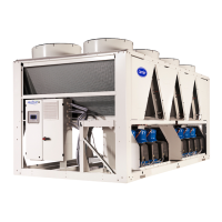
11.14 - Fan stages
Product Circuit Stage 1 Stage 2 Stage 3 Stage 4
Variable drive on 30RBP/30RQP
or Option 17
30RB/RBP 170R A EV11 - - - All
30RQ/RQP 165R-180R B EV21 EV21+EV22 - - All
30RB/RBP 190R-210R-230R-270R A EV11 EV11+EV12 - - All
30RQ/RQP 210R-230R-270R B EV21 EV21+EV22 - - All
30RB/RBP 310R-340R A EV11 EV11+EV12 - - All
30RQ/RQP 310R-330R B EV31 EV31+EV21 EV31+EV21+EV32 - All
30RB/RBP 380R 30RBP 410R
A EV11 EV11+EV12 EV11+EV12+EV22 - All
B EV31 EV31+EV32 EV31+EV32+EV21 - All
30RQ/RQP 370R-400R
A EV11 EV11+EV12 - - All
B EV21 EV21+EV31 EV21+EV31+EV22 EV21+EV31+EV22+EV32 All
30RBP 450R-480R A EV21 EV21+EV11 EV21+EV11+EV22 - All
30RQ/RQP 430R-470R B EV31 EV31+EV41 EV31+EV41+EV32 EV31+EV41+EV32+EV42 All
30RBP 550R A EV11 EV11+EV21 EV11+EV21+EV12 EV11+EV21+EV12+EV22 All
30RQ/RQP 520R B EV31 EV31+EV41 EV31+EV41+EV32 EV31+EV41+EV32+EV42 All
30RBP 610R
A - - - - All
B - - - - All
30RBP 670R-720R
A - - - - All
B - - - - All
30RBP 770R-800R
A - - - - All
B - - - - All
30RBP 870R-950R
A - - - - All
B - - - - All
11.15 - Variable speed ventilation
(30RBP/30RQP units)
The variable speed drives on the fans are used to optimise the
efficiency of the unit depending on the conditions of use
(air temperature, circuit capacity) and hence improve the seasonal
eciency (SEER and SCOP).
All fans in the same refrigerant circuit are actuated and controlled
by a single variable speed drive.
Therefore, they operate together at the same rotation speed.
All variable-speed fans are controlled by the unit controller.
For an EC fan option, each variable-speed fan is equipped with
its own variable drive.
The speed is controlled independently for each refrigerating circuit,
This rotation speed at full-load or partial load for each circuit is
controlled by an algorithm that continuously optimises the
condensing (cooling mode) or evaporation (heating mode)
temperature, to obtain the best unit energy eciency (EER and
COP) whatever the operating conditions.
Fan motor electrical protection
The motors of a same circuit are electrically protected by the
variable frequency drive in case of short-circuit, locked rotor or
general overload.
Each variable frequency drive follows a variable current
characteristic, based on the frequency from 5 to 50 Hz and the
number of fans controlled.
In case of fan failure (e.g. motor disconnected) the variable
frequency drive will detect this problem and an alert will be sent
to the user interface.
Refer to the unit’s control manual for the list of alarms.
11.16 - SmartVu
TM
control
The interface for the SmartVu
TM
control has the following
characteristics:
- It has a 4.3-inch colour screen.
- It is intuitive and user-friendly. Clear and concise information
is presented in the local language (8 languages available).
- The complete menu can be adapted to the various users
(end customer, maintenance personnel, manufacturer
engineers).
- Unit setting and use are secure. Password protection
prevents unauthorised access to advanced parameters.
- No password is required to access the most important
operating parameters.
11 - MAIN COMPONENTS OF THE UNIT AND OPERATING CHARACTERISTICS
52

 Loading...


