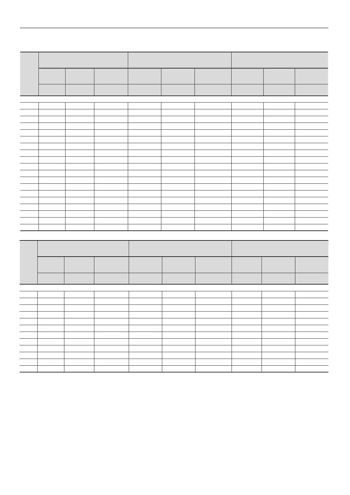
Table of minimum and maximum cable sections (per phase) for connection to the units
30RB-
RBP
Max. connectable section
(1)
Calculation of favourable case:
No. 13 Perforated horizontal raceway or no. 17
self-supporting cable - PR (90 °C) - 45 °C
Calculation of unfavourable case:
No. 41 Closed conduit - PR (90 °C) - 45 °C
Tightening
torque
Connection
hole
Recommended
max. lug width
Section
(2)
Max. length
for a voltage
drop < 5%
Cable type
(3)
Section
(2)
Max. length
for a voltage
drop < 5%
Cable type
(3)
Nm mm
qty x mm²
(per phase)
m -
qty x mm²
(per phase)
m -
Standard unit
170R 15 M8 25 1x50 180 90 °C 2x25 190 90 °C or 70 °C
190R 15 M8 25 1x50 180 90 °C 2x35 210 90 °C or 70 °C
210R 15 M8 25 1x70 190 90 °C 2x35 210 90 °C or 70 °C
230R 15 M8 25 1x70 190 90 °C 2x50 240 90 °C or 70 °C
270R 15 M8 25 2x35 170 90 °C 2x70 260 90 °C or 70 °C
310R 50 M10 32 2x50 190 90 °C 2x70 260 90 °C or 70 °C
340R 50 M10 32 2x50 190 90 °C 2x70 260 90 °C or 70 °C
380R 50 M10 32 2x70 200 90 °C 2x95 270 90 °C or 70 °C
410R 50 M10 32 2x70 200 90 °C 2x95 270 90 °C or 70 °C
450R 50 M10 32 2x70 200 90 °C 2x120 290 90 °C or 70 °C
480R 50 M10 32 2x95 210 90 °C 2x120 290 90 °C or 70 °C
550R 50 M10 32 2x95 210 90 °C 2x150 300 90 °C or 70 °C
610R 50 M10 32 2x120 220 90 °C 2x185 310 90 °C or 70 °C
670R 50 M10 32 2x150 220 90 °C
2x240
320 90 °C or 70 °C
720R 50 M10 32 2x150 230 90 °C
2x240
320 90 °C or 70 °C
770R 50 M10 32 2x185 240 90 °C
4x120
300 90 °C or 70 °C
800R 50 M10 32 2x185 240 90 °C
4x150
310 90 °C or 70 °C
870R 50 M10 32 2x240 240 90 °C
4x150
310 90 °C or 70 °C
950R 50 M10 32 2x240 240 90 °C
4x185
300 90 °C or 70 °C
30RQ-
RQP
Max. connectable section
(1)
Calculation of favourable case:
No. 13 Perforated horizontal raceway or no. 17
self-supporting cable - PR (90 °C) - 45 °C
Calculation of unfavourable case:
No. 41 Closed conduit - PR (90 °C) - 45 °C
Tightening
torque
Connection
hole
Recommended
max. lug width
Section
(2)
Max. length
for a voltage
drop < 5%
Cable type
(3)
Section
(2)
Max. length
for a voltage
drop < 5%
Cable type
(3)
Nm mm
qty x mm²
(per phase)
m -
qty x mm²
(per phase)
m -
Standard unit
165R 15 M8 25 1x50 180 90 °C 2x25 190 90 °C or 70 °C
180R 15 M8 25 1x50 180 90 °C 2x35 210 90 °C or 70 °C
210R 15 M8 25 1x70 190 90 °C 2x35 210 90 °C or 70 °C
230R 15 M8 25 1x70 190 90 °C 2x50 240 90 °C or 70 °C
270R 15 M8 25 2x35 170 90 °C 2x70 260 90 °C or 70 °C
310R 50 M10 32 2x50 190 90 °C 2x70 260 90 °C or 70 °C
330R 50 M10 32 2x50 190 90 °C 2x70 260 90 °C or 70 °C
370R 50 M10 32 2x70 200 90 °C 2x95 270 90 °C or 70 °C
400R 50 M10 32 2x70 200 90 °C 2x95 270 90 °C or 70 °C
430R 50 M10 32 2x70 200 90 °C 2x120 290 90 °C or 70 °C
470R 50 M10 32 2x95 210 90 °C 2x120 290 90 °C or 70 °C
520R 50 M10 32 2x95 210 90 °C 2x150 300 90 °C or 70 °C
(1) Connection capacities actually available for each machine. These are dened according to the connection terminal size, the electrical box access opening dimensions,
and the available space inside the electrical box.
(2) Selection simulation result considering the hypotheses indicated.
(3) If the maximum calculated selection is for a 90 °C cable type, this means that a selection based on a 70 °C cable type can exceed the connection capacity actually
available. Special attention must be given to selection.
The protection against direct contact at the electrical connection point is compatible with the addition of fanout cables. The installer must determine whether these are
necessary based on the cable sizing calculation.
Note: The currents considered are given for a machine tted with a hydraulic module operating at the maximum current.
6 - ELECTRICAL CONNECTION
26
 Loading...
