Installation
18 RTU Open
NOTE Output relay contacts rated at 3A, 24V maximum. Install pilot relays required by application.
NOTE
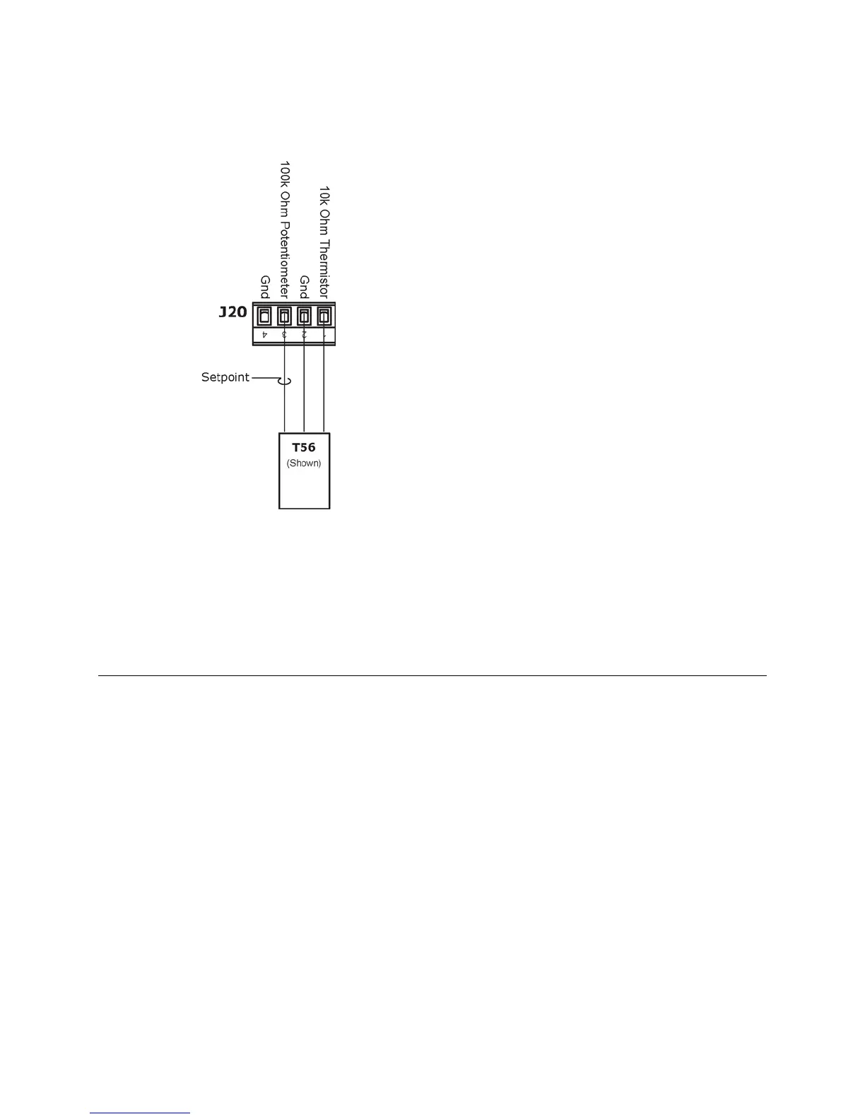
J20 Analog Inputs 10 and 11 are reserved for a 10k Ohm space temperature sensor with an
optional 100k Ohm offset potentiometer used for setpoint adjustment.
Wiring sensors to inputs
You may wire various sensors to the RTU Open's inputs. See the table below for details.
NOTE This document gives instructions for wiring the sensors to the RTU Open. For specific mounting and
wiring instructions, see the Carrier Sensors Installation Guide.
All field control wiring that connects to the RTU Open must be routed through the raceway built into the corner
post. The raceway provides the UL-required clearance between high-and low-voltage wiring.
1 Pass the control wires through the hole provided in the corner post.
2 Feed the wires through the raceway to the RTU Open.
3 Connect the wires to the removable Phoenix connectors.
4 Reconnect the connectors to the board (where removed).

 Loading...