Introduction
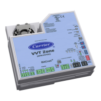
2 VVT Zone Controller
0
1
3
4
5
2
78
9 6
0
1
3
4
5
2
78
9 6
HWV
Gnd
Analog
Output
Gnd
T55 (Opt)
RH/CO2
Gnd
SAT
Gnd
REMOTE
LED
Gnd
Rnet +
Rnet -
+12V
R n e t
BACnet Power
On
4
3
2
1
-
+
Batt
CR2032
10's
1's
Thermistor
T55 (Opt)
RH/CO2
Factory Defaults
Rnet
MSTP
Output
24V Max,
1A Max
Conductors Only
Class 2
Use Copper
26Vdc, 0.1A, 3W
14VA, 0.58A
24Vac, 50-60 Hz
This product was designed
CAUTION:
to be mounted inside the
building envelope.Warranty
voided if mounted outside.
Interconnect the Outputs of
Different Class 2 Circuits.
To ReduceThe Risk of Fire
or Electric Shock, Do Not
CAUTION:
BACnet
VVT Zone
®
AO: 0-10 Vdc
5mA Max
Local
Access
Short pins
Enable SAT
Enable SAT and REMOTE
CW CCW
Motor
Error
Run
Power
0-5Vdc
Made in USA
Inputs
TxRx
MSTP Baud
76.8k38.4k19.2k9600
Damper release button inside
TYPE: 002101
E143900
88FO
Enclosed Energy
Management Equipment
R
Net +
Net -
Shield
Ground
24V ac
Rnet+
Sense
+12V
Rnet-
Gnd
FAN
Power for B.O.s
BUS
HEAT1
HEAT2
(OPN-VVTZC)
BT485
NOTE This document gives instructions for field-installation of a VVT Zone Controller in an i-Vu Open Control
System. However, VVT Zone Controllers are available factory-mounted to Carrier’s round and rectangular
dampers. Damper assemblies have an integrated duct temperature sensor.
 Loading...


