Introduction
4 VVT Zone Controller
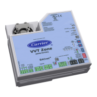
Status indicators LED's indicate status of communications, running, errors, power, and digital
outputs
Environmental operating
range
0 to 130° F (-18 to 54°C), 0 to 90% relative humidity, non-condensing
Storage temperature range -24 to 140°F (-30 to 60°C), 0 to 90% relative humidity, non-condensing
Physical UL94-5VA plenum rated enclosure for installation in plenum (or other space
for environmental air) in accordance with NEC Section 300.22 (c) and (d)
Overall dimensions A:
B:
C:
7 in. (17.8 cm)
6-1/32 (15.4 cm)
6 in. (15.24 cm)
Mounting dimensions D:
E:
F:
G:
H:
5-5/8 in. (14.3 cm)
4-9/16 in. (24.3 cm)
1-5/16 in. (3.3 cm.)
7/8 in. (2.2 cm)
1-5/16 in. (3.3 cm)
Panel depth 2-1/2 in. (6.4 cm) minimum
Shaft dimension Minimum shaft diameter: 3/8 in. (.95 cm.)
Maximum shaft diameter: 1/2 in. (1.27 cm)
Minimum shaft length: 1 3/4 in. (4.45 cm)
Weight 1.7 lbs (0.77 kg)
BACnet support Conforms to the Advanced Application Controller (B-AAC) Standard Device
Profile as defined in ANSI/ASHRAE Standard 135-2004 (BACnet) Annex L
Listed by UL-916 (PAZX), cUL-916 (PAZX7), FCC Part 15-Subpart B-Class A, CE
EN50082-1997
 Loading...


