RS – Multi-Stage, I-280
Centrifugal Pump 280 – 16.03.EN
17
All openings of the assembled unit components are
closed and must only be opened when required during
installation.
All blank parts and surfaces of the pump are oiled or
greased (silicone-free oil and grease) to protect them
against corrosion.
VII. INSTALLATION.
A. LOCATION. The pump assembly should be
located in an area that will permit periodic inspection
and maintenance. Head room and access should be
provided and all units should be installed in a dry
location with adequate drainage. The discharge piping
should be direct with as few elbows and fittings as
possible.
The pump assembly should be installed as close to the
fluid as possible. A short, direct suction pipe can be
used to keep suction losses at a minimum. If possible,
locate the pump so fluid will flow by gravity to the
suction opening. The discharge piping should be direct
with as few elbows and fittings as possible. The total Net
Positive Suction Head Available (NPSHA), which
includes the suction lift and pipe friction losses, must be
greater than the Net Positive Suction Head Required
(NPSHR) by the pump.
B. HANDLING.
CAUTION
Use a hoist with adequate lifting capacity.
Do not pick up the complete unit by the motor
or the pump shafts or motor lifting eyes.
If the pumping unit slips out of the sling
arrangement, it may cause injury to personnel
and/or damage to the pumping unit.
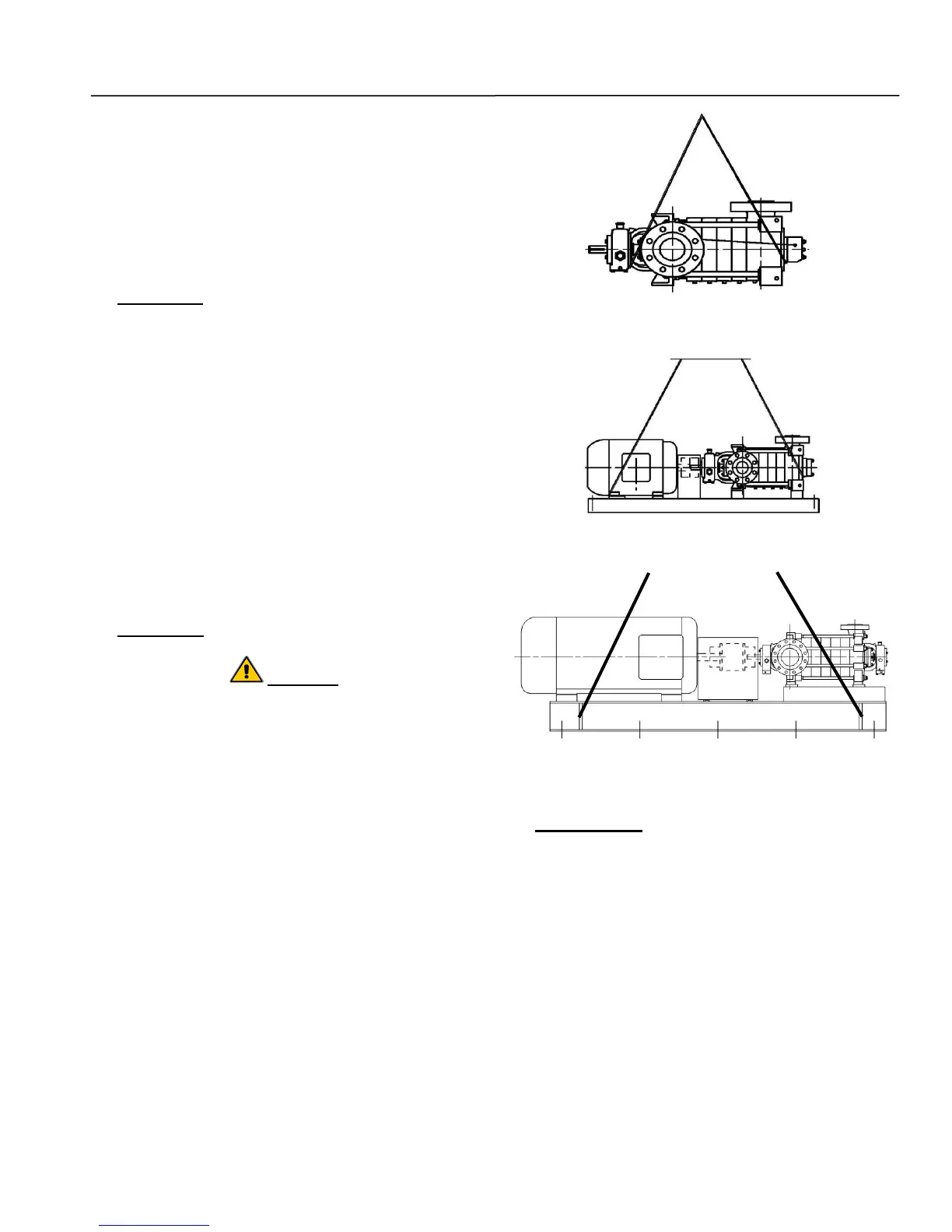
Moving the unit requires proper preparation and
handling. Always make sure that the pump or the
pumping unit remains in a horizontal position while
being moved and cannot slip out of the transport
suspension arrangement. Use a sling for pumps without
baseplates, refer to Figure 4. To lift a horizontal
mounted unit, a hoist or suitable lifting device should be
attached to each corner of base structure, refer to
Figure 5. To lift a horizontal mounted unit, a hoist or
suitable lifting device should be attached to each lifting
lug on the base structure, refer to Figure 6. The
individual motor may be lifted using proper eyebolts
provided by the manufacturer, but these should not be
used to lift the assembled unit.
Figure 4. Sling Position for Moving Pump
Figure 5. Sling Position for Moving Pumping Unit
Figure 6. Sling Position for
Moving Pumping Unit with Lifting Lugs
C. FOUNDATION. Make sure that the concrete
foundation has set firmly before placing the unit on it. Its
surface must be truly horizontal and even. The
foundation bolts must be inserted in the base holes. The
foundation should be 3 to 6 inches wider and longer
than the base, have a level surface, and be of sufficient
mass to prevent vibration and form a permanent rigid
support for the unit. The best foundations are concrete
with anchor bolts of adequate size embedded in the
foundation in pipe sleeves having an inside diameter 2-
1/2 times larger than the bolt diameter. This will allow for
accurate positioning of the unit. Keep the concrete
surface clean, yet rough.
Hydraulic Institute (HI) recommends a foundation
capable of absorbing vibration at least five times the
weight of the pumping unit and to form a permanent,