RS – Multi-Stage, I-280
Centrifugal Pump 280 – 16.03.EN
20
F. COUPLING ALIGNMENT. The pump and motor
are connected by a coupling. Alignment is necessary
when the pump or motor are removed from the base.
The coupling should NOT be reconnected until the
alignment has been completed. Always check the
coupling alignment after shipping. The following is how
to check the coupling alignment.
NOTE
Refer to coupling manufacturer’s manual for
instructions regarding shaft alignment and
recommended installation limits.
Soft Foot – The equipment must rest flat on its
base. If one or more feet of the pump or motor
are shorter, longer, or angled in some way to
prevent uniform contact (a condition commonly
known as “soft foot”) it must now be corrected.
To improve the life of the coupling, the shafts must be
aligned to minimize deflection of the flexing elements.
Shaft alignment is required in the axial, parallel, and
angular directions, with each of these values not to
exceed the recommended installation limits. Shaft
alignment can be measured using various established
methods, including Laser Alignment, Reverse Dial
Indicator, and Rim and Face.
The motor and pump shafts must be accurately aligned
as any misalignment can cause damage to the coupling,
motor, or pump. When the shafts are in correct
alignment, the coupling hubs will be on a common axis,
concentric with each other, and at the correct distance
apart. If the coupling hubs are misaligned, it is general
practice to adjust the driver to the pump. Insert full
shims under the feet or supports of the motor and
tighten fastening bolts until correct alignment is
achieved.
1. Move the pump or motor to achieve acceptable
alignment. When properly aligned, the disc
packs will be centered and approximately
parallel to their mating flange faces and the
flexing elements will have little visible waviness
when viewed from the side.
NOTE
Refer to the coupling manufacturer’s manual for
recommended installation limits for Parallel,
Angular, and Axial alignment.
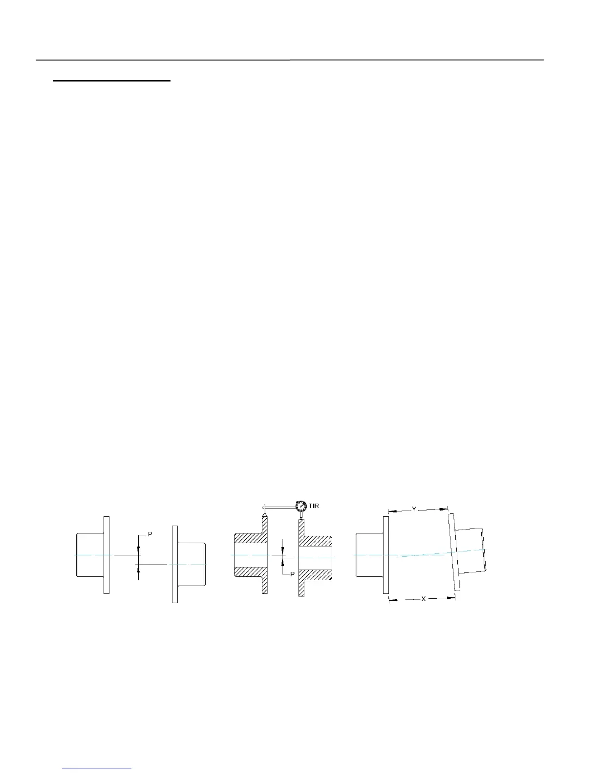
2. The “Parallel Misalignment” value (P) is the
offset between the centers of the hubs, as
shown in Figure 9.
3. When the Parallel Offset is measured by
rotating the hubs in unison with dial indicators
as shown in Figure 9, the Total Indicator
Reading (TIR) should be divided by (2) to
calculate (P).
4. It should be noted that parallel offset measured
on the hub surfaces includes misalignment of
the equipment shafting plus any variation (TIR)
in the hubs. This may be helpful to consider
during problem solving for alignment difficulties.
5. The “Angular Misalignment” value is the
maximum difference between the
measurements X and Y taken at opposite ends
of the hub flanges, as shown in Figure 9.
Figure 9. Coupling Alignment
Parallel Offset Misalignment
Parallel Offset (TIR)
Measurement