RS – Multi-Stage, I-280
Centrifugal Pump 280 – 16.03.EN
34
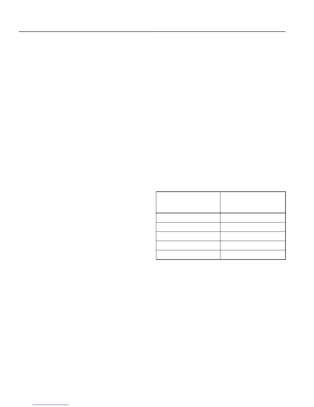
and the low reading of the outside diameter
of the back impeller (2A or 2X) wear ring
exceeds double the new maximum
clearances given in Table 16, replace the
back wear ring according to Section XI,
Paragraph G.
10. Check rotor TIR and balance as follows:
a. Check shaft TIR on roller bearing “V” blocks
in (3) spots, coupling end, middle and
discharge end of shaft.
b. Install O-ring (89X) on suction end for
standard design or discharge end for
optional design. Install key (32X). Install the
sleeve (14A, standard design or 14X,
optional design).
c. Install snap ring (176). Install bearing
spacer (78). Install ball bearings (16,
standard design or 18, optional design)
back to back, meaning lettering on the outer
race facing each other.
d. Install first bearing jam nut (22) and torque
to 3 ft/lbs. Install second bearing jam nut
and torque to 30 ft/lbs. making sure that the
first bearing jam nut does not tighten with
the second bearing jam nut.
e. Install spacer sleeve (14D, standard design
or 14E, optional design) on shaft (6).
f. Install impeller (2A, standard design or 2X,
optional design). Install the interstage
sleeve (58) on the shaft (6). Repeat until
you have no more impellers to put on the
shaft.
g. Install sleeve (14X) on shaft (6). Install shaft
washer (28, standard design) on shaft and
first jam nut (614, standard design), torque
jam nut to 30 ft/lbs. Note where the coupling
shaft keyway is oriented. This is important
to getting the best rotor TIR.
h. Check rotor TIR by placing an indicator on
the impeller wear ring wearing surface and
the interstage sleeves (58), rotate the shaft
(6) slowly for reading. Rotor TIR must be
.006 inch or less. Check coupling end of
shaft to verify less than .003 inch TIR.
i. To achieve the best TIR, loosen the jam nut
(614, standard design), rotate shaft (6) 90
degrees, torque jam nut and recheck and
record all TIRs again. When best TIR has
been achieved, mark both ends of shaft with
an arrow pointing down.
j. Tape ball bearings (16, standard design or
18, optional design) so they don’t spin on
shaft (6) and are covered so no debris gets
in during the balancing of the rotor.
k. Dynamic balance rotor to G-6.3 spec.
l. IMPORTANT: Mark all impellers, sleeves,
interstage sleeve gaskets, and keys with
numbers in the order they were staged
while dismantling according to sequence for
rotor balbance. Disassemble rotor.
Table 16. Factory Wear Ring Clearance (Inches)
New Maximum
Diametrical Clearance
(Casing & Diffuser)