RS – Multi-Stage, I-280
Centrifugal Pump 280 – 16.03.EN
42
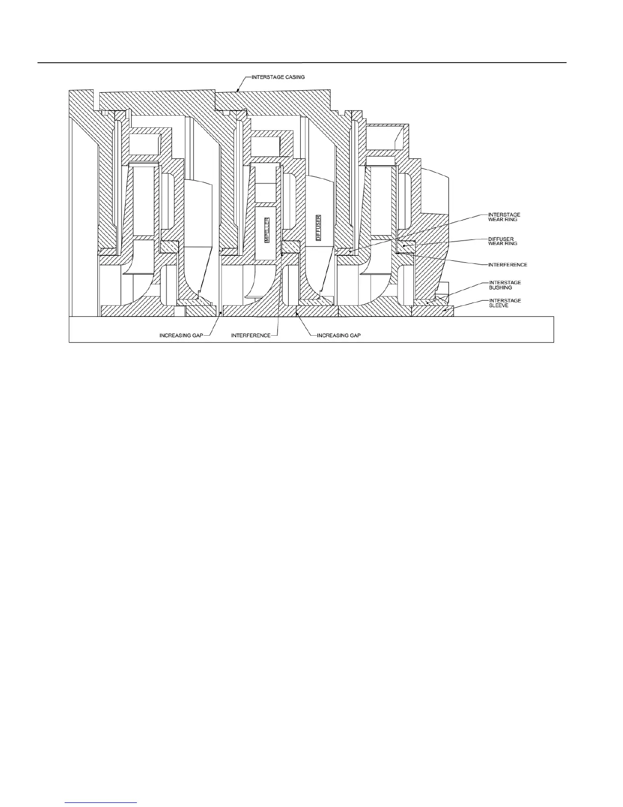
Figure 12. Mechanical Seal Not Torqued Interference
NOTE
Every gap that is left in the stack-up to achieve
that stage final axial impeller alignment will
compound to every stage after it and will have
to be subtracted from all final axial impeller
alignments.
23. Install spacer sleeve (14D) onto shaft (6).
24. Install key (32X) into keyway on shaft (6).
25. Mark shaft (6) and end of sleeve (14A) to
determine location of key aligning key to
keyway.
26. Lubricate and install sleeve O-ring (89X) and
slide into groove on shaft (6).
27. Install sleeve (14A) onto shaft (6).
28. Lubricate and install casing O-ring (89D) onto
suction casing (9).
29. Install suction casing (9) and tap into place
against interstage casing (111), insure proper
flange orientation of suction casing. Confirm
gland studs (630) are installed in suction casing.
30. Install tie bolts (173), flat washers (645) and tie
bolt hex nuts (616) and temporarily torque hex
nuts to 50 ft/lbs.
31. Install spacer sleeve (14G). Install bearing
frame (99) on suction casing (9) temporarily with
two bolts (600). Install bearing (16) and install
one jam nut (22), leave loose.
NOTE
Remove pump from vertical position and place
in horizontal position either on a milled flat
surface or a pump base.
32. Loosen the tie bolt hex nuts (616) and tap with
soft mallet both suction and discharge casing
feet flat to the milled surface or the base.
NOTE
Ensure that the pump feet are on a milled flat
surface or the base before tie rod hex nuts are
torqued.
33. Tighten tie bolt hex nuts (616) firmly and evenly.
Refer to Table 14 for recommended torque
requirements.