RS – Multi-Stage, I-280
Centrifugal Pump 280 – 16.03.EN
45
Suction Case Wear Ring (7A).
The suction case (9) must be removed from the base to
replace the first stage wear ring (7A). To replace the first
stage wear ring (7A) follow these steps:
When pump is handling hazardous fluid,
extreme care must be taken to ensure safety of
personnel when attempting to drain pump and
piping before disconnecting the pumping unit.
Suitable protection devices should be used
and/or protective clothing should be worn.
1. Disassemble pump per Section XI, Paragraph
C, steps 1 through 15.
2. Remove suction case (9) from base and take
suction case and first stage impeller (2A) to a
work area with access to machine shop
equipment.
3. Remove the first wear ring (7A) from the suction
case (9). This can best be accomplished on a
lathe for composite wear rings. Hardened metal
wear ring can be pried out of case.
4. Press the new first wear ring (7A) into the
suction case (9). The beveled edge of the first
wear ring is installed away from the first stage
impeller (2A).
5. Place impeller (2A) on an arbor and mount
between centers in a lathe or a grinder. Indicate
front outside impeller hub to within 0.002 TIR
maximum to be sure the arbor and impeller are
running square.
6. Turn the front outside wear ring surface of the
impeller (2A) until a 63 RMS or better finish is
obtained.
7. Measure the outside diameter of the front
impeller wearing surface and record this value.
See measurement instructions in Section XI,
Paragraph D.
8. Mount the suction case (9) with new first wear
ring (7A) installed in a lathe. Indicate female
rabbet to within 0.002 TIR maximum.
NOTE
When replacing first wear ring with the standard
first wear ring, (part number beginning with
"00") machining in step 9 is not required. When
replacing first wear ring with the undersize first
wear ring (part number beginning with "US")
machining in step 9 is required.
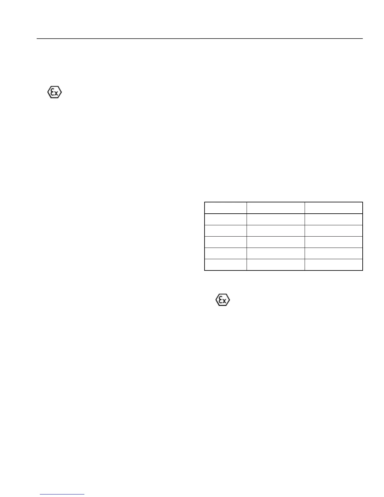
9. If replacing with an undersized wear ring, bore
wear ring (7A) to within the specified tolerance
listed in Table 18 over the recorded size of the
outside diameter of the front impeller wearing
surface.
10. Reinstall suction case (9) on base.
11. Reassemble pump. Refer to Section XI,
Paragraph F, steps 18 through 65.
Table 18. New Wear Ring
Diametrical Clearance Limits (Inches)
Diffuser Wear Ring (7X).
When pump is handling hazardous fluid,
extreme care must be taken to ensure safety of
personnel when attempting to drain pump and
piping before disconnecting the pumping unit.
Suitable protection devices should be used
and/or protective clothing should be worn.
1. Complete Section XI, Paragraph C, steps 1
through 15 before continuing.
2. Remove interstage case (111) with front wear
ring (7X) still installed and the impeller (2X) to a
work area with access to machine shop
equipment.
3. Remove the front wear ring (7X) from the
interstage case (111). This can best be
accomplished on a lathe for composite wear
rings. Hardened metal wear rings can be pried
out of case.
4. Press the new front wear ring (7X) into the
interstage case (111).