DISTRIBUTION SYSTEMS - HIGH-FLOW HYDRAULIC POWER SYSTEM
Control valve - Install (A.16.A.14 - F.10.A.15)
435, 445, 445CT
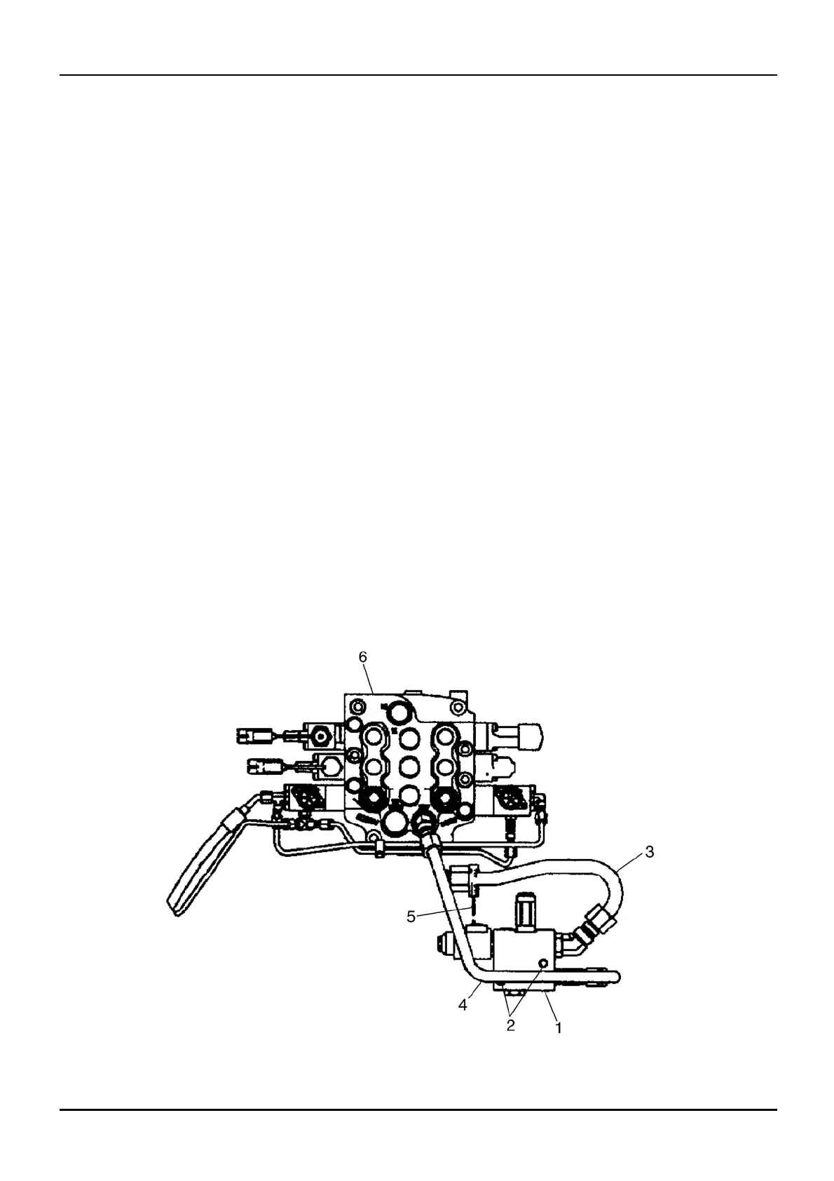
1. Install the control valve (1) into the machine
mounting location.
2. Install the control valv e mount ing bolts (2) into
the control v
alve (1)and tighten the control valve
mounting bolts (2) .
3. Connect the electrical harness (5) to the control
valve electrical connection.
4. Start the vacuum pump. Reservoir - Apply
vacuum (A.10.A.22 - F.35.A.50)
5. Remove the caps from the fittings and the plugs
from th e hydrau lic lines.
6. Install the hydraulic line (3) on to the con tr ol valve
(1)and tighten the fittings.
7. Install the hydraulic line (4)onto the control valve
(1)and
tighten the fittings.
8. Stop the vacuum pump.
9. Remove the v acuum p ump from the hydraulic
reservoir.
10. Start an d run the engine at low idle for 2 to 5 minutes
and c heck for any leaks.
11. Operate High-Flow switch to verify valve functions.
1
2.
C
heck the oil level in the hydraulic reservoir and
add hydraulic oil as required. Reservo ir - Fillin g
(A.10.A.22 - F.60.A.10)
bs04d135 1
1 04/05/2005
A.16.A / 12