DISTRIBUTION SYSTEMS - ELECTRICA L POWE R SYSTEM
Connector - Testing (A.30.A.87 - G .40.A.20)
435, 445, 445CT
NOTE: For wiring diagram refer to Wiring harness - Electrical schematic frame 06 (A.30.A.88 - C.20.E.06)
Wiring harne ss - Electrical sc hematic frame 04 (A.30.A.88 - C.20. E.04)
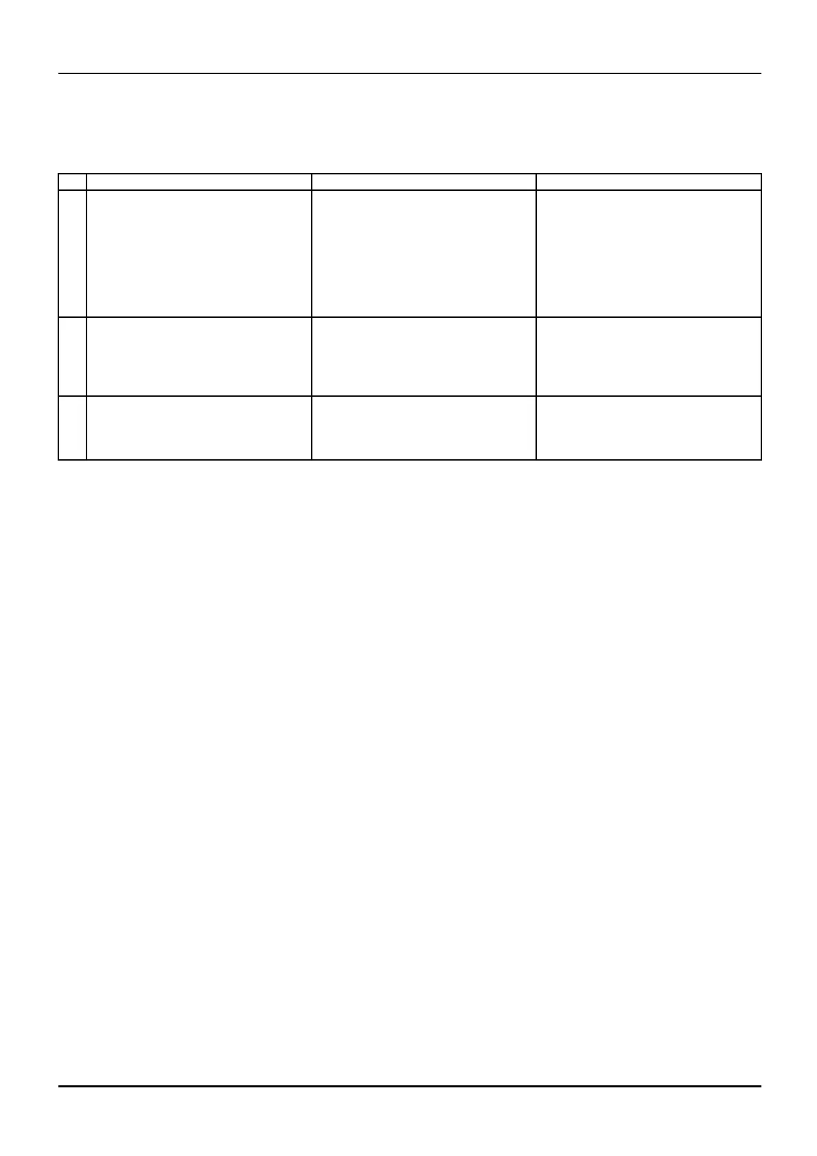
N°
Te st Point Expected Result
Other Result (Possible Cause)
1 Disconnect the 26 pin connector
from the instrument cluster. Make
sure the ROPS is in the latched
position. Have another person sit in
the ope rators seat. P lace the se at
bar in the down position.
Terminal 14 in the connector to
ground.
85 to 90 ohms coil resistance
Check the circuit between the
connector and the interlock relay
coil. Also check the interlock relay.
Also chec k circuit for g round wire
178E (B).
2
Turn the key switch to the ON
position.
Terminal 12 in the connector to
ground.
12 volts
Check the circuit between the
connector and the seat switch. Also
check the seat switch.
Also check circuit for wire 13 0B (R )
to the 1 5 amp buss bar f use.
3
Terminal A (258) in the connector to
ground.
12 volts
Check the circuit between the
connector and the brake pressure
switch. Also check the brak e
pressure switch
1 04/05/2005
A.30.A / 102