Chapter 8: Geometry Application 169
“
t0” and “t1” specify the range of movement of point A on side CD. The initial default values are t0 = 0 and
t1 = 1. During animation, the length of CD is considered to be one unit. The default values specify that
movement of point A is from start point C (point where length equals 0) up to end point D (point where length
equals 1).
Changing the value of
t0 to 0.5, for example, causes point A to move from the middle of side CD to point D.
Changing the value of t0 to −1, causes point A to begin at a point outside side CD (in this case, at a point a
distance equivalent to the length of side CD) and ending with point D.
Traces:
This item shows the specified trace point. Tapping [Remove] cancels the trace point setting.
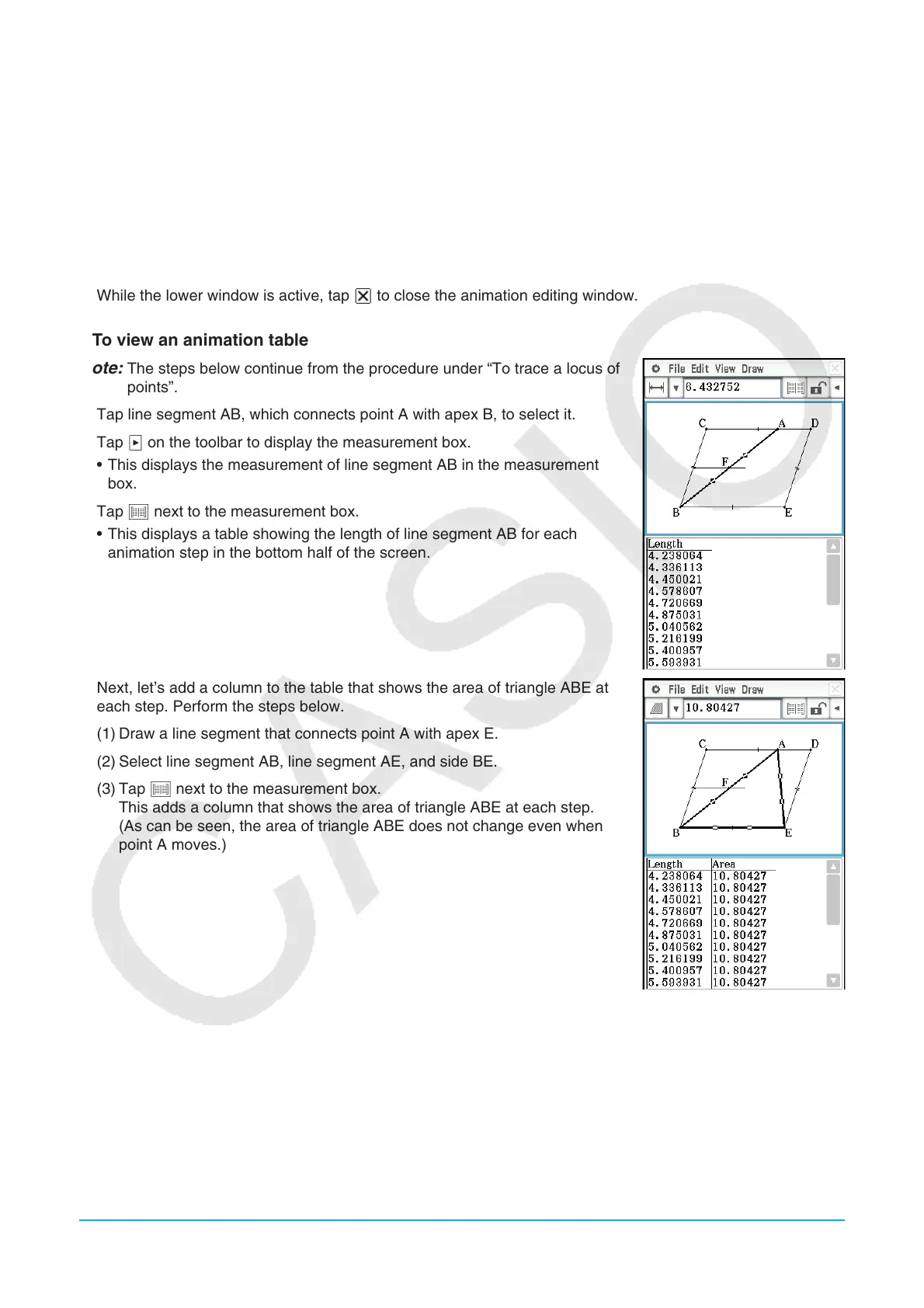
3. While the lower window is active, tap C to close the animation editing window.
u To view an animation table
Note: The steps below continue from the procedure under “To trace a locus of
points”.
1. Tap line segment AB, which connects point A with apex B, to select it.
2. Tap u on the toolbar to display the measurement box.
• This displays the measurement of line segment AB in the measurement
box.
3. Tap # next to the measurement box.
• This displays a table showing the length of line segment AB for each
animation step in the bottom half of the screen.
4. Next, let’s add a column to the table that shows the area of triangle ABE at
each step. Perform the steps below.
(1) Draw a line segment that connects point A with apex E.
(2) Select line segment AB, line segment AE, and side BE.
(3) Tap # next to the measurement box.
This adds a column that shows the area of triangle ABE at each step.
(As can be seen, the area of triangle ABE does not change even when
point A moves.)
 Loading...