- 8 -
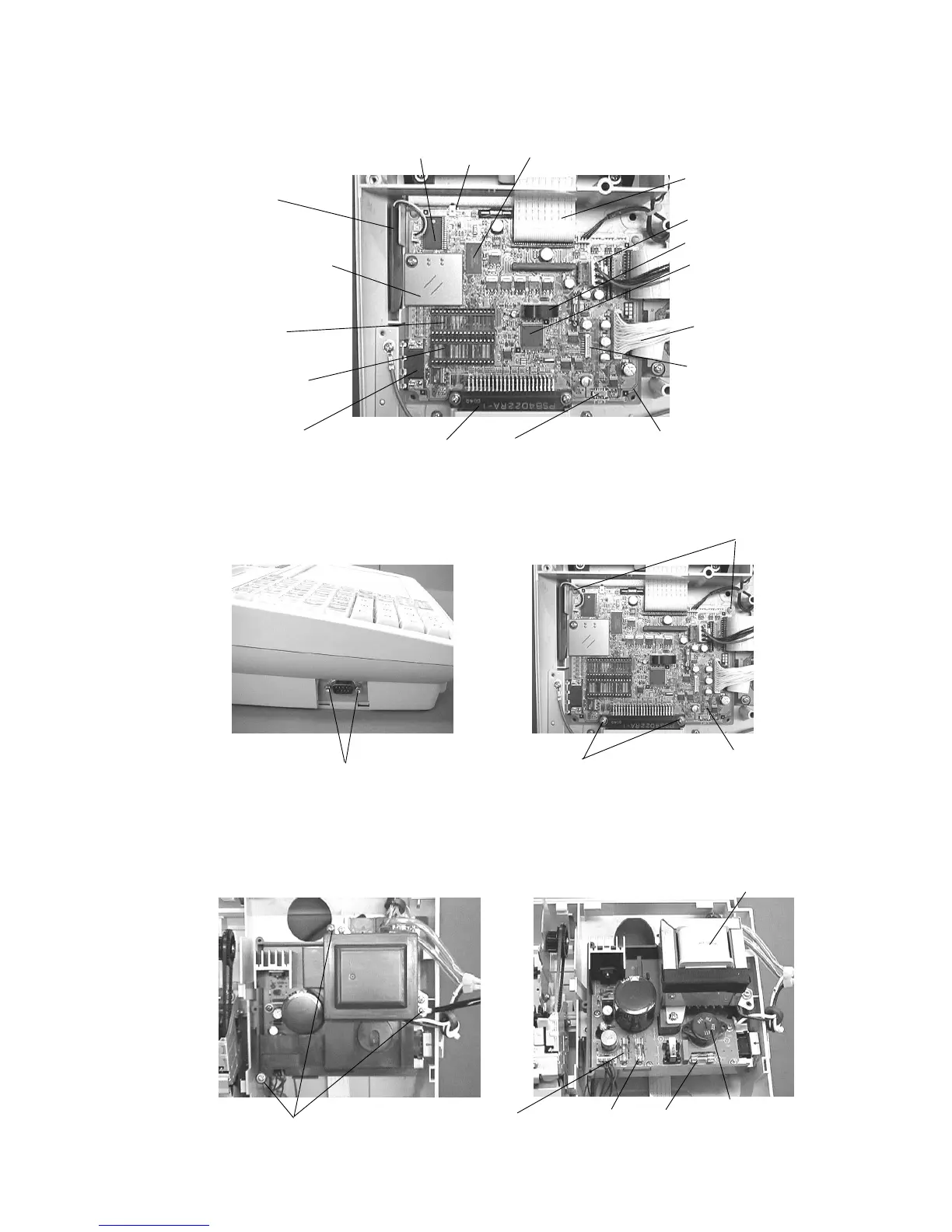
6. To remove the Main PCB, release the 2 screws of point A and 2 locking supporters of point B
and the COM1 port outside screws.
Remove 2 screws for COM 1 port.
5. The each parts of the Main PCB are located as shown in the picture.
Battery
Flash ROM 1 (2 M bytes)
Main PCB
Flash pack connector
for Memory cassette
RAC-9
RAM 1 (128 K bytes)
Flash ROM 2 (512 K bytes)
(NOT USED)
RAM 4
(NOT USED)
RAM 3
(Option RAM-610)
COM 1 port
CPU
Buzzer
Printer cable
Display cable
Power supply connector
Reset Switch
Point A
Remove 2 screws.
Point B
Remove 2 screws.
7. Power supply unit cover is removed by 3 screws. And, the 3 Fuses are located as shown in the
picture.
Main PCB
Remove the 3 screws.
Then, remove the power supply cover.
Power transformer
Voltage selector
Normally, Do not change the
Voltage position.
(NOT USED FOR USA,Canada)
Fuse F1
250V 1A
Fuse F2
250V 2A
Fuse F3
250V 400mA
(NOT USED FOR TK-6500)
Clerk key connector
(Not mounted for USA, Canada)
Keyboard select switch
(Set to "F" for TK-6500.)
NOTE: RAM2 (128 K bytes) is located on
the back side of Main PCB.