- 16 -
Memory map
00000h CPU internal memory
Mask ROM 128K
RAM 5K
0FFD0h External I/O Mapping 16bytes
0FFE0h
20000h
RAM1 128 K bytes
RAM2 Oprion RAM3 Oprion RAM4
128 K bytes 512 K bytes 512 K bytes
40000h Bank0 Bank1 Bank2 Bank3 Bank4 Bank5 Bank6 Bank7 Bank8 Bank9 Bank10 Bank11 Bank12 Bank13 Bank14 Bank15 Bank16 Bank17
RAM
Banked area
64 K bytes
Flash2 Flash2 Flash memory pack 2 M bytes Accelerator Expansion Memory area
Flash pack 512K bytes 512 K bytes Board
Expansion memory
256 K bytes Bank0 Bank1 Bank0 Bank1 Bank2 Bank3 Bank4 Bank5 Bank6 Bank7 Share CE
+ A16 to A19
80000h
Bank area
Flash 1 384 K bytes 16 M bit
(for
A0000h Application 8 M bit
program area) 4 M bit
2 M bytes Bank0 Bank1 Bank2 Bank3 Bank4
00,01 08,09 14,15 20,21 26,27 Block No.
(07,06) (0F,0E) (19,18) (17,16) (1F,1E) (Memory Block)
C0000h
02,03 10,11 16,17 22,23 28,29
(05,04) (0D,0C) (11,10) (15,14) (1D,1C)
E0000h 04,05 12,13 18,19 24,25 30,31
Common area (o3,02) (0B,0A) (09,08) (13,12) (1B,1A)
128 K bytes
Block
06,07
FFFFFh (00,01)
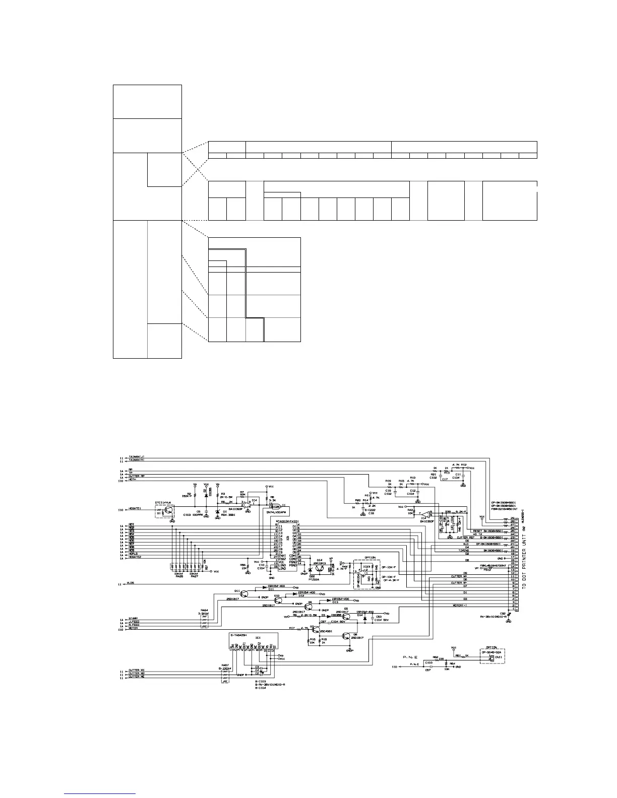
6-8. Printer drive circuit
The printer drive circuit is as follows:
IC5 (MTA001M-F4101) is the head pin driver IC. And, the Transistors Q6,Q7 and Q8 are the
motor drive circuit. The IC1 (TA8429H) is the auto paper cut driver circuit. For TK-6500, the
auto-paper cut drive circuit is not used.