CassidaPRO Zeus: Service Manual
2018 Cassida Corporation. All rights reserved.
Rev: 09/05/2018
cassidapro.com/partner/
CURRENCY AND FUNCTION CHECKS
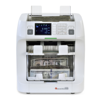
When you press Key [2] you will then see each magnetic head individually. Below is an
example of the MHL on a passing sensor.
2.3.
In this test, you should confirm whether magnetic sensor output is within range, and falls
within the expected detection envelope for each note scanned.
Abnormal - If the signal seems flat, out of range, or outside of the scan
envelop check:
· Magnetic Sensors
· Mecha PBA
· Cable Connections
3) Check Position Sensors and Main motor
• Select this display by pressing in Service Menu -> [1] Diagnosis -> [5]
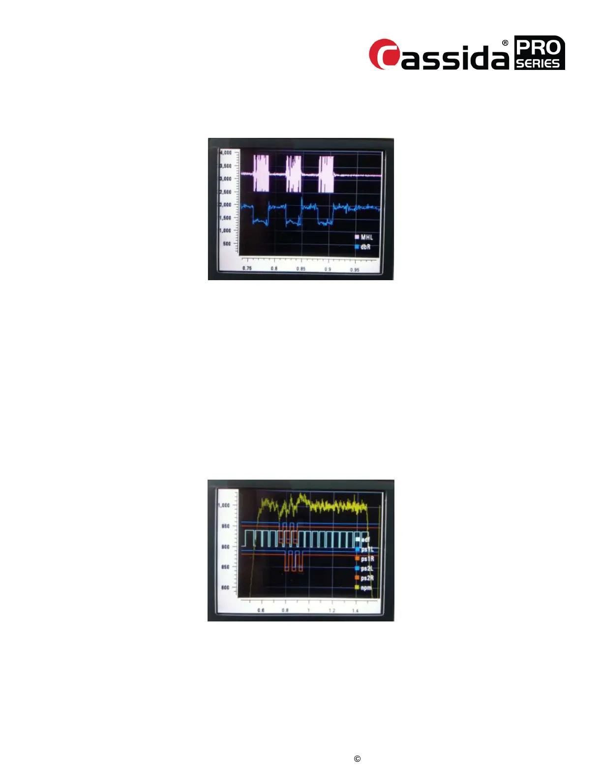
Scanning Quality -> [3]Position Sensors. The below image shows a passing
scan and position.
• Default screen pictured below:
This graph displays adf encoder (light blue), ps1L (blue) and ps2L (blue in lower position),
ps1R (red) and ps2R (red in lower position), npm (yellow) signals.
In Fig. 6, the machine’s counting speed is plotted along the vertical axis called NPM (Notes
Per Minute), and horizontal axis shows times. The teal square wave is the signal from the
encoder used to determine physical position of the ADF rollers. The red and blue pulses for
each PS1 and PS2 sensor are the sensed position of the note in the bill transport path.
[Fig. 6]
 Loading...
