System Overview
IM-ChipEncoder-Series-Rev. 2 Page 9 ©2022 Celera Motion
ChipEncoder Series
Installation Manual and Reference Guide
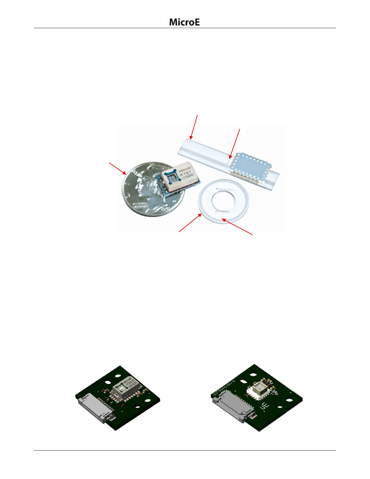
3.2 Linear and Rotary Glass Scales
The scales available for the ChipEncoder:
Linear Glass Scales
Rotary Glass Scales
Examples of scales (shown with ChipEncoder CE300)
3.3 Evaluation PCB
There are two alternatives for initially creating/designing a PCB to test with the ChipEncoder:
Design your own PCB and install the ChipEncoder to it
Purchase the Eval PCB and install the ChipEncoder to it (see Section 7.5 Evaluation Board
for more details). Once testing is successful, then a production PCB can be designed.
The ChipEncoder must be mechanically aligned to the scale. Alignment can be confirmed using an
Oscilloscope (see install procedure). See Section 8.0 Order Guide for details on ordering the Eval
PCB.
ChipEncoder Evaluation Board
Evaluation PCB (CE300-4-PCB or CE300-40-PCB)
Evaluation PCB (CE-40GC-PCB)