ChipEncoder Installation
IM-ChipEncoder-Series-Rev. 2 Page 12 ©2022 Celera Motion
ChipEncoder Series
Installation Manual and Reference Guide
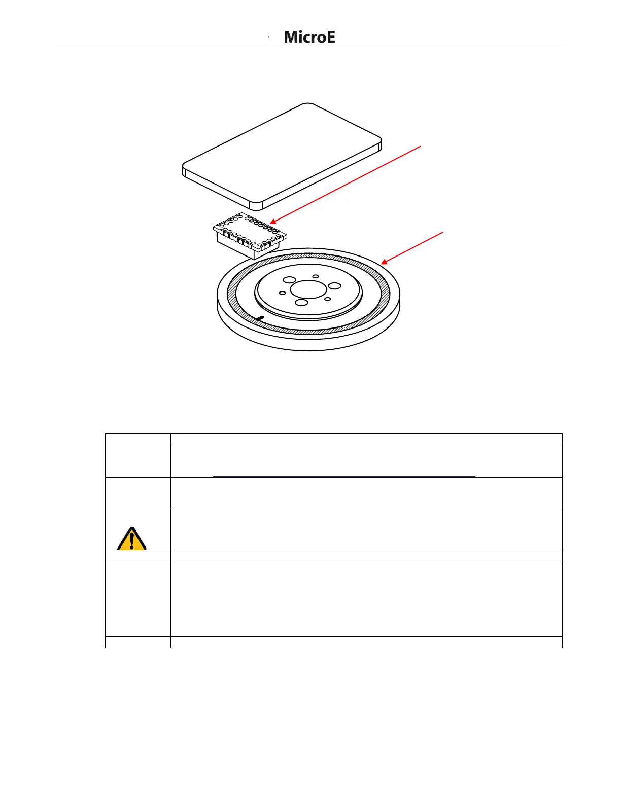
4.2.2 Rotary Scale Installation
The rotary scale must be installed before installing the ChipEncoder.
Note: The encoder may be powered during this procedure.
Perform the following steps to install the ChipEncoder.
Install the ChipEncoder on a printed circuit board (PCB) to the electrical and mechanical
specifications listed in the ChipEncoder interface drawings, which are available on the MicroE
website: http://www.microesystems.com/resource/product-documentation.
Attach the hub/scale assembly to the rotary device. The reflective surface of the scale must
face the sensor. Refer to the datum on the interface drawings for either end or center index
orientation.
Attach the scale to the slide using adhesive. Be sure that the grating surface of the scale
faces the sensor.
Caution: Damage can result from the ChipEncoder contacting the grating.
Apply power to encoder if not already powered on.
ChipEncoder outputs can be viewed using a digital oscilloscope. See Section 7.2 Output
Signals Descriptions for the A, B, and Index Window signals. The ChipEncoder should not
require additional alignment as long as the PCB and mechanical components have been
fabricated and assembled according to the mechanical dimensions and tolerance specified in
the applicable interface drawings.
Go to Section 4.3 Encoder Alignment for additional details for alignment.
For alignment verification, see Technical Note TN-103: Alignment of Rotary Scales.