ChipEncoder Installation
IM-ChipEncoder-Series-Rev. 2 Page 10 ©2022 Celera Motion
ChipEncoder Series
Installation Manual and Reference Guide
4.0 ChipEncoder Installation
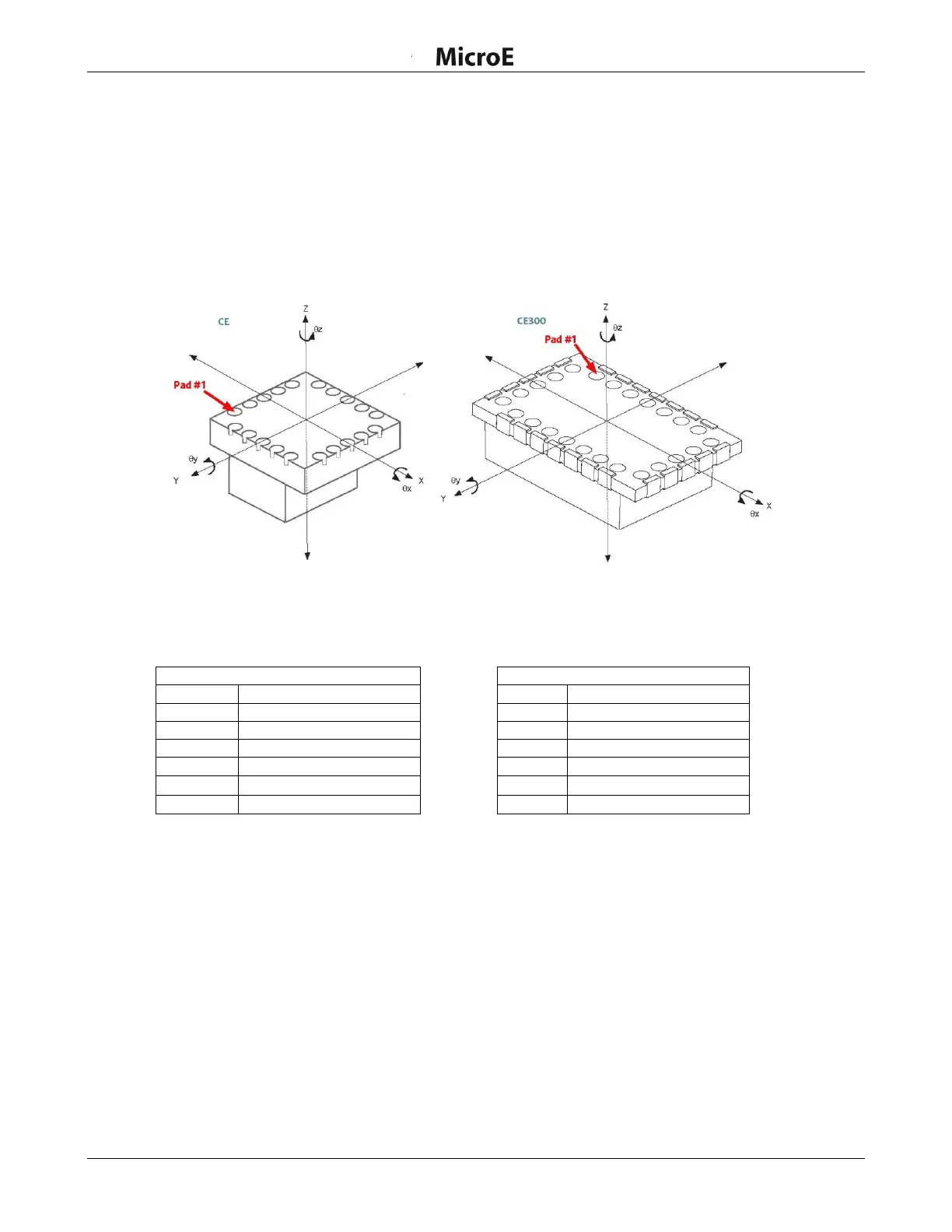
4.1 Mounting Orientation and Tolerances
Refer to the following specifications when installing and aligning the ChipEncoder. See Section 7.2
Output Signals Descriptions in the Appendix for pad identification.
Orientation
Tolerances
Mounting with Linear Scales
Mounting with Rotary Scales
Note: Tolerance for each axis is specified independently, assuming nominal alignment in other axes.