EasyManua.ls Logo

Celera Motion MicroE ChipEncoder Series - Output Signals Descriptions

Default Icon
30 pages
Print Icon
To Next Page IconTo Next Page
To Previous Page IconTo Previous Page
Loading...
Appendix
IM-ChipEncoder-Series-Rev. 2 Page 19 ©2022 Celera Motion
ChipEncoder Series
Installation Manual and Reference Guide
7.2 Output Signals Descriptions
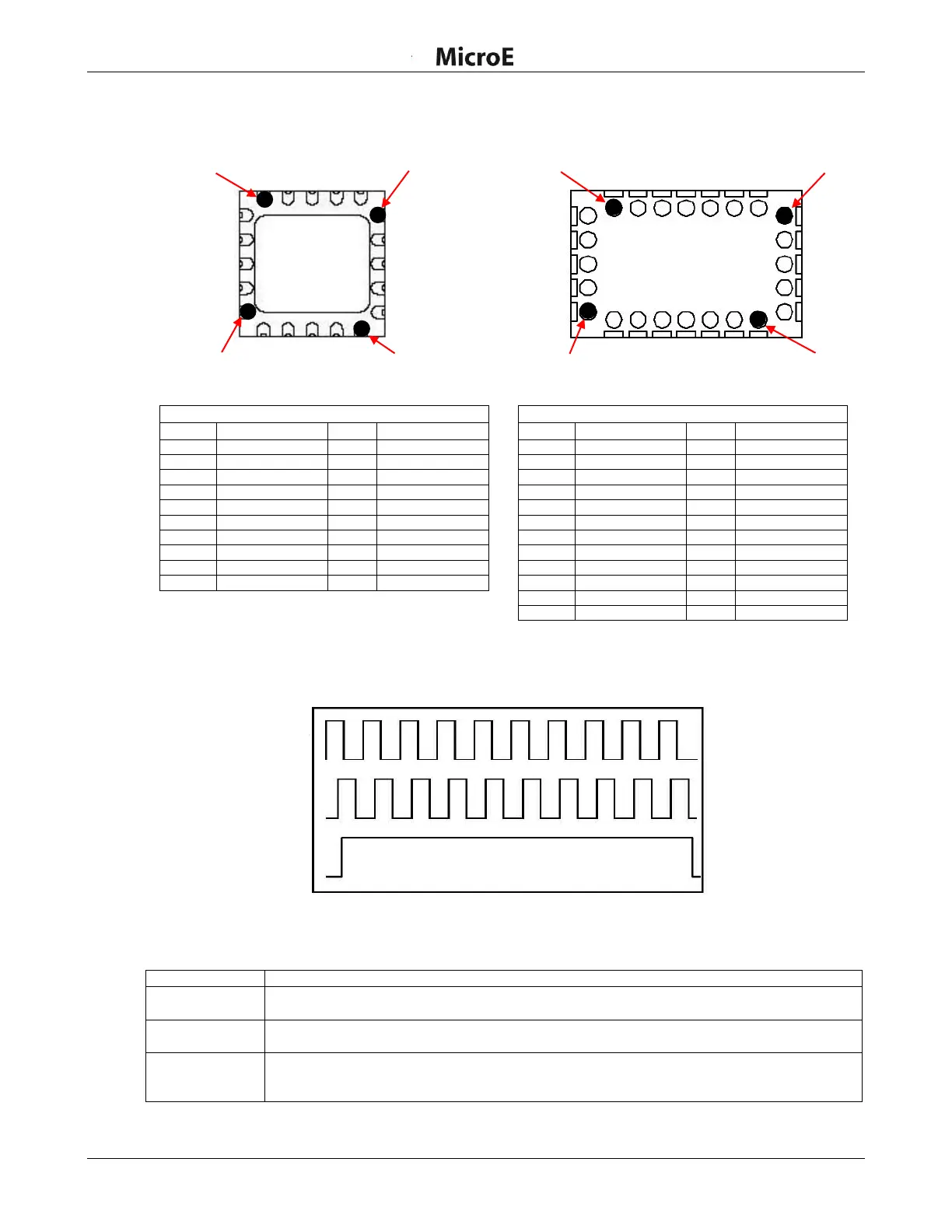
CE (6mm x 6mm ChipEncoder)
CE300 (7mm x 11mm ChipEncoder)
CE Output Signals
Pad
Function
Pad
Function
1
+5VD
11
No Connect
2
No Connect
12
CP+
3
SIN+
13
No Connect
4
AN
14
No Connect
5
+5VA
15
Index Window-
6
DC1
16
Index Window+
7
No Connect
17
A-
8
DC2
18
A+
9
GND
19
B-
10
CA
20
B+
CE300 Output Signals
Pad
Function
Pad
Function
1
Index Window-
13
AN
2
GND
14
SIN+
3
No Connect
15
No Connect
4
No Connect
16
No Connect
5
CP+
17
No Connect
6
+5VA
18
GND
7
No Connect
19
+5VD
8
GND
20
B+
9
DC2
21
B-
10
No Connect
22
A+
11
DC1
23
A-
12
No Connect
24
Index Window+
A+, B+, and Index Window+ Outputs from 40X Encoder
Description of signals:
Signal
Description
A+/A-
Digital quadrature outputs. Signals are RS-422 compatible square waves. Pulses are 90° out
of phase with B+/B- outputs.
B+/B-
Digital quadrature outputs. Signals are RS-422 compatible square waves. Pulses are 90° out
of phase with B+/B- outputs.
Index Window+/
Index Window-
The Index Window defines one particular fringe on the grating surface. The Index Window
signal is a TTL compatible pulse, and is approximately 40 um wide. Note that this signal is not
synchronized to the A or B signals.
PAD 1
PAD 8
PAD 13
PAD 11
PAD 20
PAD 1
PAD 6
PAD 16
Index+
A+
B+