Appendix
IM-ChipEncoder-Series-Rev. 2 Page 26 ©2022 Celera Motion
ChipEncoder Series
Installation Manual and Reference Guide
7.6 Recommended Signal Termination
Digital/Analog Outputs
Note: Maximum cable length is 5 m. Contact MicroE Applications Engineering if longer lengths are
required.
Note: It is not recommended that the Sin+ signal be transmitted on your cable. This may introduce
noise into the ChipEncoder.
7.7 Customer Interface
Cable Requirements
Customer cables that interface to the ChipEncoder Series must have the following characteristics:
Twisted pairs with 120 ohm characteristic impedance
Shielding connected to the sensor's outer shield
7.8 RS-422 Compatibility
ChipEncoder Series Encoders are RS-422 compatible. Encoder signals are “sending end terminated”
and customer receiving terminations are not required.
For more details, see the following Tech Note: Proper Termination of Digital Incremental Encoder
Signals.
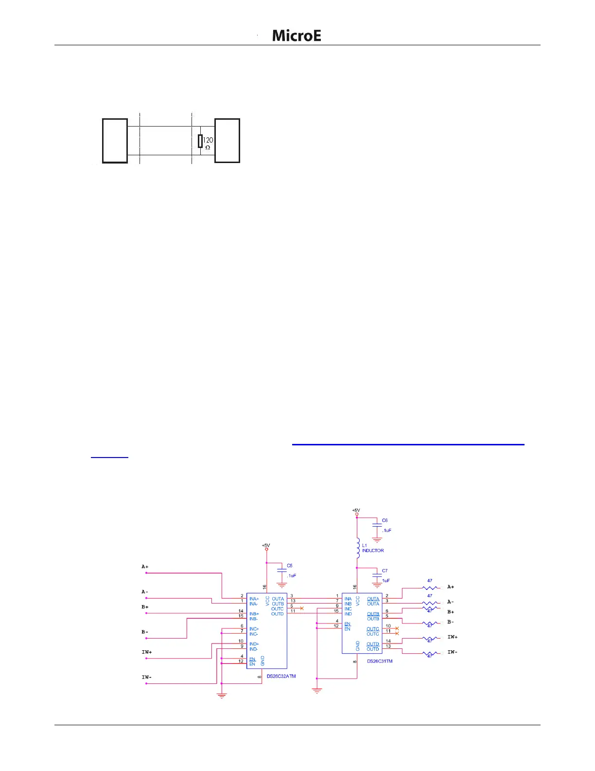
Optional RS-422 compliant circuitry for long cable runs in harsh electronic environments is illustrated
below:
ChipEncoder
Series Encoder