Before Installation
IM-ChipEncoder-Series-Rev. 2 Page 5 ©2022 Celera Motion
ChipEncoder Series
Installation Manual and Reference Guide
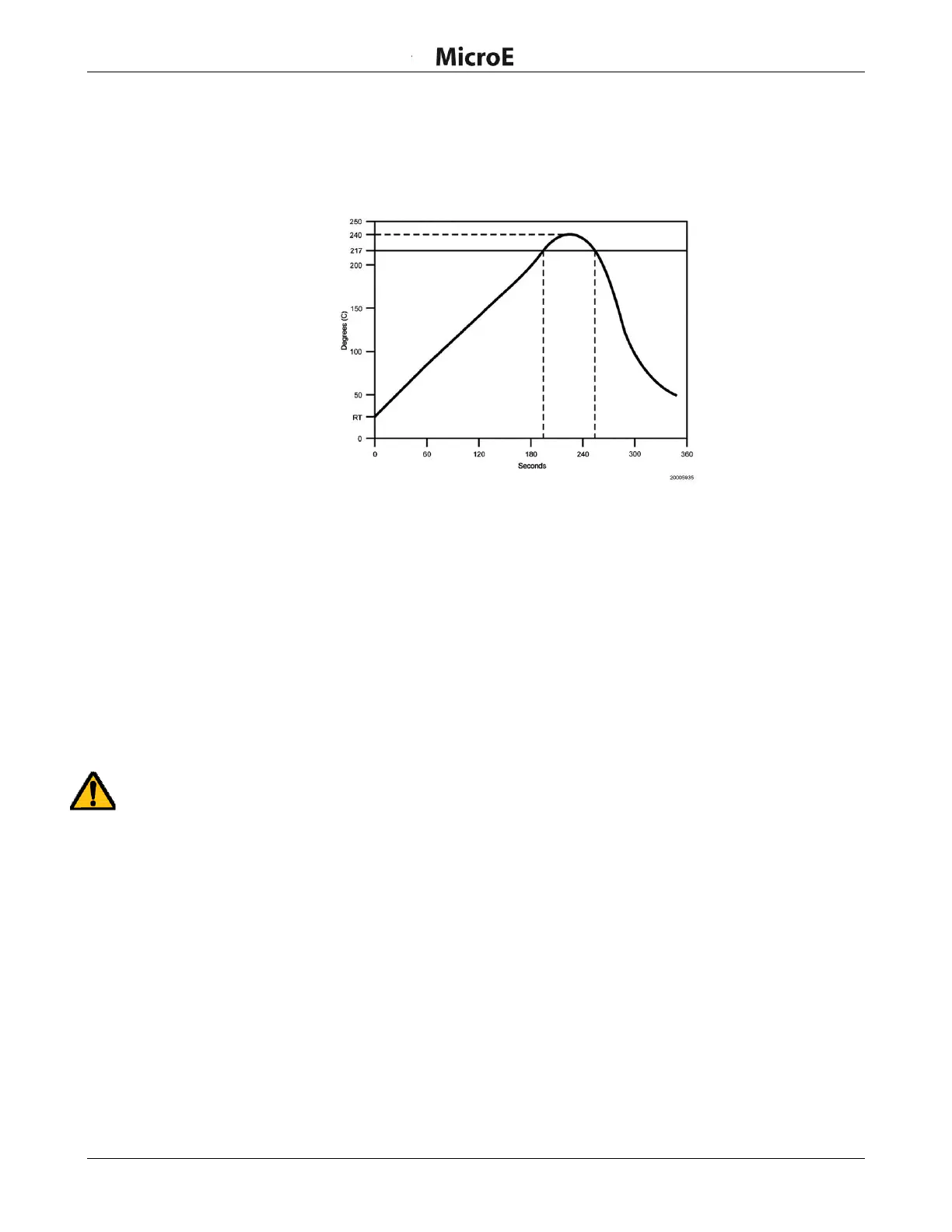
2.4 Solder Paste Recommendation and Reflow Profile
The ChipEncoder can be soldered to a PCB using industry standard techniques. The diagram below
illustrates the recommended reflow temperature profile.
Lead-Free Solder Reflow
Use a temperature-controlled convection or IR reflow oven and SAC305 solder paste with no-clean flux
in either air or an inert atmosphere (N
2
). The temperature should be measured on the carrier board close
to the ChipEncoder parts and should not exceed 260°C.
The ChipEncoder has soldered devices under the cover. The rate of heating and cooling must be
controlled so that it does not exceed 5°C per second to avoid thermal stressing of the devices.
The ChipEncoder inputs and outputs are pre-tinned palladium silver pads with the typical spacing
between adjacent input/output pads of 0.2 mm (0.008 inches). The pads are pre-tinned with SAC305
solder alloy. Solder material with good slump characteristics should be chosen to ensure that solder
does not bridge or short during pre-heating in the reflow process.
Hand Soldering
Hand soldering can cause damage. Hand soldering guidelines:
CE300: Do not hand solder. Castellations are for electrical testing only.
CE: Hand solder only if necessary.
Reflow Solder
Temperature Profile