chapter 5000
page 51
1,2 - 2,0 t A.C.
SERVICE MANUAL
Electric
036-0410-07
CODE ALARM DESCRIPTION
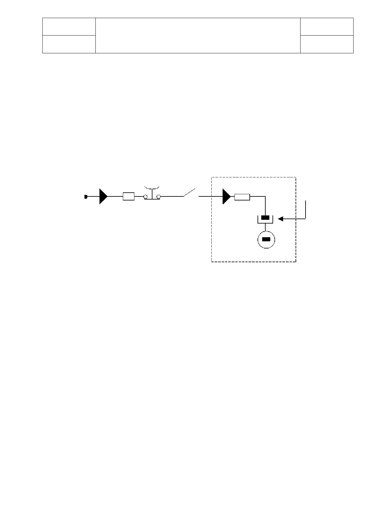
10 CAPACITOR When the key is switch ON, the inverter tries to charge the capacitor
CHARGE through a power resistance, and check if the capitor are charged within a
timout. If they do not charge, an alarm is signalled;
the main contactor is not closed.
- Check the negative connection.
- Check voltage in the input of the key. Battery voltage must be present.
- Execute a short circuit between the key terminals.
- Replace the traction unit.
11 HIGH Master or Slave or both temperatures are higher than 75°C. The maximum
TEMPERATURE current is reduced proportionally to the temperature increase. At 100°C the
max current of both inverters is reduced to zero. If the alarm is signalled
when the controller is cold:
- Replace the traction unit.
12 MOTOR This warning is signalled if the sensor of the right motor is opened (digital
TEMPERATURE sensor)
- identify the on wiring diagram the connector J1 (J7 on I/O card):
- If between the positive pin (1) and negative pin (2) there is 5V = the
sensor is open
- If between the positive pin (1) and negative pin (2) there is 0V = the
sensor is closed
If it occurs when the motor is cold, check:
a: the sensor is closed
b: between the positive pin (1) and negative pin (2) of the connector J1 (J7
on I/O card) there is 0V
- if "a" and "b" conditions take place replace the logic unit .
- 5V must be present on the positive pin (1) and negative pin (2) in the I/O
card connector J7 (with the wiring diagram J1 connector disconnected).
In the opposite case, replace the I/O card.
Vb D1 F1 PB1
Traction
power
capacitor
S1