chapter 5000
page 29
1,2 - 2,0 t A.C.
SERVICE MANUAL
Electric
036-0410-07
See wiring diagram
CONNECTOR DESCRIPTION
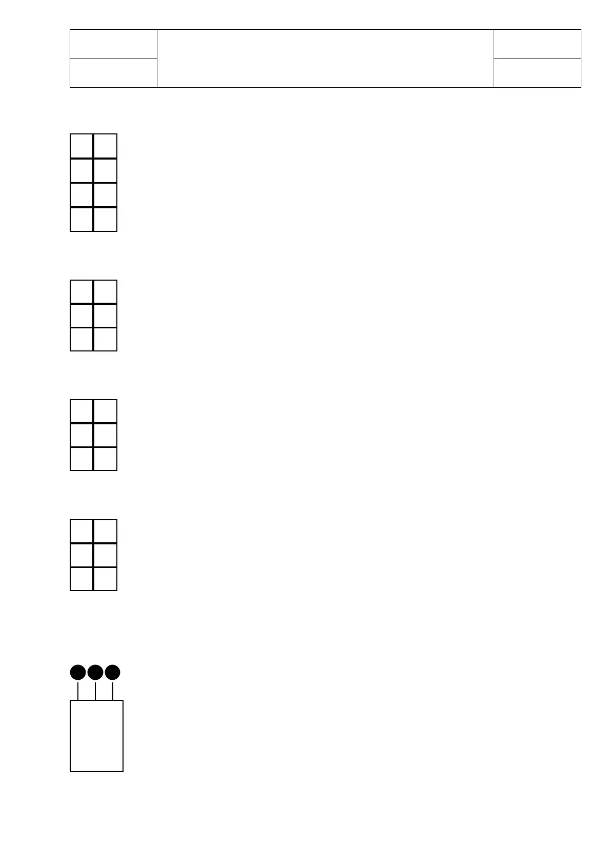
Connector 1
It is a connector to 8 Pins used for controlling the lights.
PINS 1-5 are connected together = 24 Volt.
PINS 2-6 are connected together = output of the stop lights 0-24 Volt. It is a proportional
value given that the voltage depends on the temperature of the lamp bulbs
PINS 3-7 are connected together = output of the reverse lights 0-24 Volt.
It is a proportional value given that the voltage depends on the temperature of the
lamp bulbs
PINS 4 negative signal
PIN 8 24 Volt input for the converter 24-5 Volt located on the card.
Connector 2
It is a connector to 6 Pins.
PIN 1 CAN L
PIN 2 CAN H
PIN 3 GND
PIN 4 Not used
PIN 5 Out put 24 Volt
PIN 6 Not used
Connector 3
It is a connector to 6 Pins.
PIN 1 CAN L
PIN 2 CAN H
PIN 3 GND
PIN 4 Not used
PIN 5 Out put 24 Volt
PIN 6 Not used
Connector 4
It is a connector to 6 Pins.
PIN 1 CAN L
PIN 2 CAN H
PIN 3 GND
PIN 4 Not used
PIN 5 Out put 24 Volt
PIN 6 Not used
Led 5
shows that the light card is fed but is not receiving the CAN-BUS input
Converter 6
PIN A 24 Volt
PIN B GND
PIN C 5 Volt
Resistance 7
It is the input resistance. R17 = 100 Ohm 3 Watt.
The connectors 2-3-4 are connectors for the CAN-BUS and they can be inverted without
problem
41
5
2
63
41
52
63
51
62
73
84
A
BC
24 V / 5 V
41
52
63