chapter 5000
page 6
1,2 - 2,0 t A.C.
SERVICE MANUAL
Electric
036-0410-07
2
3
1
7
3
5
4
2
6
1
7
8
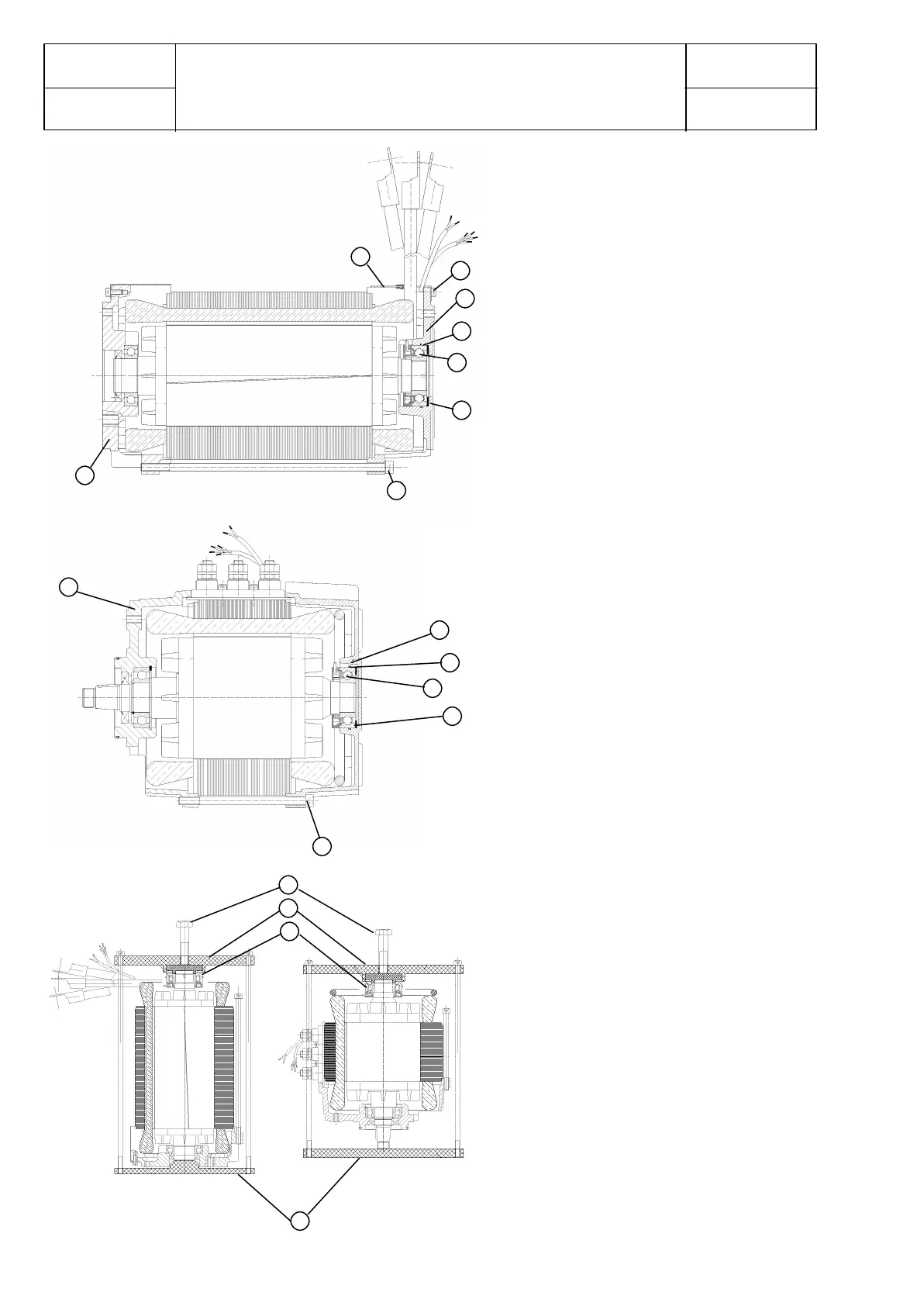
Disassembly
Disconnect the motor electrically and remove it.
Open and remove the 4 cylinder head screws
(M8x250 for the lifting motor, M8x130 for the
traction motor) Pos. 1 between non drive end
plate Pos. 2 and drive end plate Pos. 3. For the
lifting motor: take off the metal cover Pos. 4
after loosening the cylinder head screws Pos. 5
of the aluminium non drive end plate Pos. 2.
Take off the aluminium non drive end plate Pos.
2 with slight punches by means of a rubber
mallet. Remove the cable strap (which fastens
the sensor bearing cable).
Carefully remove the 2 clamping pins of the
temperature sensor from the 9-pin plug (pin
5+6). Remove the sensor bearing Pos. 6 by
means of an extractor (caution! do not damage
the centering of the shaft).
Assembly
Put the motor shaft with drive end side against
the plate (Pos 9); there should be no pressure
to the drive end bearing ! Put the sensor
bearing on the shaft (Pos 6). Put the press on
device (Pos 10) on the inner ring of the sensor
bearing as shown in the drawing and fix the
device with the two longer screws. Press on the
sensor bearing with the screw (Pos 11):
Be shure to press only the inner (!) ring of
the sensor bearing.
Put the connection of the temperature sensor in
the 9-pin plug (pin 5+6) again. Secure the cable
of the temperature sensor and the sensor cable
by means of a cable strap at the motor
connecting cables. Examine the o-ring (62x2,0)
Pos. 7 inside the non drive end plate Pos. 2
regarding damages, if necessary exchange it.
Put in the wavy washer Pos. 8 inside the
aluminium non drive end plate Pos. 2 again. Put
the aluminium non drive end plate Pos..2 on the
motor again, pay attention to the position of the
cable of the sensor bearing. (Attention! Risk of
damaging the cable insulation). For the lifting
motor: put the metal cover on the aluminium
non drive end plate Pos. 2 again and fix it by
means of the cylinder head screws Pos. 5 with
a torque of 7 Nm. For the traction and lifting
motors: clamp the complete terminal between
the drive end plate Pos. 3 and the aluminium
non drive end plate Pos. 2 again. Put in the 4
cylinder head screws (M8x250 for the lifting
motor, M8x130 for the traction motor) Pos. 1
and tighten them with 11 Nm. torque for the
lifting motor or with 20 Nm. torque for the
traction motor
8
9
6
6
10
11
LIFTING MOTOR
TRACTION MOTOR
LIFTING MOTOR
TRACTION MOTOR