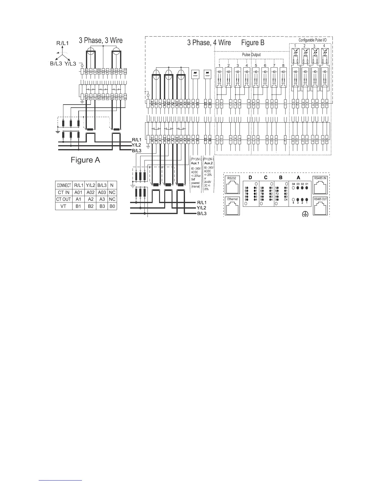
Note: For 3-phase 3-wire CT/VT operated refer to figure A
For 3-phase 4-wire CT/VT operated refer to figure B
For 3-phase 3-wire and 3-phase 4-wire connections from B5 to D9 are the same.
For self-powered variant Aux.1 (B8 and B9) supply is not available.
Figure 10: Connection Diagram
Note: One side of the CT secondary wiring should be earthed according to local practice.
The recommended size of the CT, VT and Aux power supply cable is 2.5 sq mm with lugs type as ring (M3 type)
for CT and H type for Aux and VT terminals.
In case of Prometer 100-R the internal earthing cable between the meter and the rack should also be
connected, and for this an M4 size screw is used in the meter and in the rack. The same ring type connector as
used in the CT connection can also be used.
The internal earthing cable should be about 5-10 cm in length to allow for ease of fitting and access and not
fouling with sharp edges of rack etc. Finally a proper earthing cable from rack to earth should be put up by
installer. Other accessories or shipway kit is supplied based on the requirement like seals, communication cords
etc.