IMPORTANT
NOTE
• BEFORE attempting to install, operate or maintain the operator, you must read
and fully understand this manual and follow all safety instructions.
• DO NOT attempt repair or service of your gate operator unless you are an
Authorized Service Technician.
When you see these Safety Symbols and Signal Words on the following pages, they
will alert you to the possibility of Serious Injury or Death if you do not comply
with the warnings that accompany them. The hazard may come from something
mechanical or from electric shock. Read the warnings carefully.
When you see this Signal Word on the following pages, it will alert you to the
possibility of damage to your gate and/or the gate operator if you do not comply
with the cautionary statements that accompany it. Read them carefully.
MECHANICAL
ELECTRICAL
SAFETY » SAFETY SYMBOL AND SIGNAL WORD REVIEW
TABLE OF CONTENTS
SAFETY 1-6
Safety Symbol and Signal Word Review 1
UL325 Model Classifications 2
Safety Installation Information 3
Gate Construction Information 4
Important Safety Information 5-6
INTRODUCTION 7-8
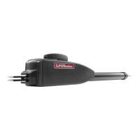
Operator Specifications 7
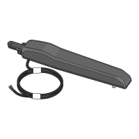
Carton Inventory 7
Additional Items Needed for Installation 8
Tools Needed 8
INSTALLATION 9-21
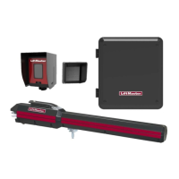
Overview of Typical Installation 9-10
Check Your Gate 11
Mounting Options 11
Manual Release 12
Determine Position of the Pull-to-Open Bracket 12
Determine Position of the "Optional" Push-to-Open Bracket 12
Assemble Gate Post Bracket (Pull-to-Open) 13
Attach Brackets to Gate Operator 13
Determine Mounting Location 14
Measuring and Marking for the Gate Bracket 14
Position Gate Operator on Gate 15
Test Gate Travel 16
Secure Post Bracket to Gate Post 16
Secure Gate Bracket to Gate 17
Warning Sign Placement 17
Standard Control Box 18-19
Large Metal Control Box (XLM) 20-21
WIRING 22-28
Connect the Gate Operator (Gate 1) to the Control Box 22
Set the Bipart Delay (Model LA400-S Only) 23
Connect the Gate Operator (Gate 2) to the Control Box (Model LA400-S Only) 24
Junction Box (Model LA400-S Only) 25-26
Connect Transformer to Control Board 27
Earth Ground Rod Installation (Optional) 28
Connect Batteries 28
ADJUSTMENT 29-33
Set DIP Switch 29
Limits 30-32
Force Adjustment 33
Timer-to-Close 33
PROGRAMMING 34
Remote Controls 34
Keyless Entry 34
Erase All Codes 34
Test 34
ADDITIONAL FEATURES 35-38
DIP Switch Settings 35
Control Inputs 36
Loop Inputs 37
Photo/Edge Inputs (P6-7-8 and 9) 37
Safety Accessories for Secondary Entrapment Protection 38
OPERATION AND MAINTENANCE 39-40
Reset Button 39
Remote Control 39
Manual Release 39
Maintenance 40
TROUBLESHOOTING 41-43
Basic Control Board Layout 41
Wiring Diagram 42
Diagnostic Codes 42
Troubleshooting Chart 43
REPAIR PARTS 44-45
Control Box 44
Gate Operator Arm 44
How to Order Repair Parts 45
WARRANTY POLICY 45
ACCESSORIES 46
TEMPLATE BACK COVER
1