47
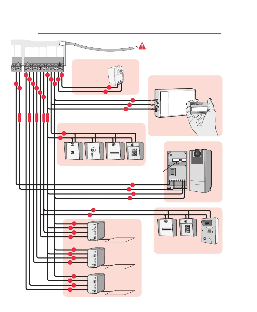
SURGE SUPPRESSOR WIRING DIAGRAM
25
23
Gnd
+24V
25
23
Gnd
+24V
CENTER
LOOP
+24 VAC
INPUT
SAFETY
LOOP
STRIKE
INPUT
BURGLAR
ALARM
INPUT
GROUND
RADIO
+24 VOLT
UL
SENSOR
13 14 15 16 17 18 19 20 21 22 23 24 25 26 27
18
17
25
23
20
19
22
21
22
21
27
26
24 VAC
40 VA
Transformer
24 VDC Exit Loop
Elite Part # A 24
24 VDC Safety Loop
Elite Part # A 24
24 VDC Center Loop
Elite Part # A 24
24 VDC Radio Receiver
Elite Part # A 1090
Green Ground Wire
13
2456
24V to
240VDC
(NC1)(C1)
LIGHT ON
DARK ON
This switch
must
be in the
"Light On"
position.
Elite Entry Phone
Works as “Open Only” Command
Works as “3 Push Button” Control
24 VDC Photocell
Elite Part # A OMRON
Push Button Card Reader
Back
Front
Digital LockKey Switch
1
2
3
Card Reader
Digital Lock
4
7
8
0
H
E
L
P
9
1
2
3
5
6
Refer to Page 20
Refer to Page 21
Refer to Page 21
Refer to Page 25
Refer to Page 21
Refer to Page 26
24
23
15
16
23
25
15
16
17
18
19
20
21
22
27
26
For Toll Free Technical Support: 1-888-ELITE-10
The Miracle-One MUST be properly grounded.
Please refer to the
“Earth Ground Rod Installation”
page 19.
24
25
23
24
25
23
N.O.
Com
N.O.
Com
Com
N.O.
Com
N.O.
24V
Relay
Radio Power
Polarity does not matter
N.O.
Gnd
+24V
Com
Ground
Ground
Ground
Ground
Ground
®