Champion Compressors Ltd. Manual No. 975203 Rev H
7
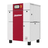
The Ci 110 uses a three phase star-delta starter panel mounted in the lid of
the compressor cabinet. This machine runs continuously, loading and
unloading as required to meet system pressure needs. An Off/Auto switch
mounted in the lid panel of the compressor is provided as a means of control.
An hour meter is provided indicating hours of operation for service intervals.
The Star-delta, Constant Speed Unload (CSU) option is available on the
Ci 75 by customer request.
Service access for your machine is excellent, with ample space provided to
allow for easy servicing of components. All the serviceable components on
the machine are located in convenient positions requiring minimum
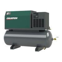
disturbance to your compressor package. All models employ a vertical fan
mounted oil cooler, and on the Ci 75 and Ci 110, an air aftercooler is also
provided as standard.
5.2 Principle of Operation
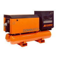
The main functional components of a Dominator rotary screw air compressor
are the integrated rotary screw airend, the drive motor and cooler assemblies.
Unlike other rotary screw air compressors, the integrated rotary screw airend
performs the task of multiple system components. This has the advantage of
reducing the number of connections between components, and also reducing
system complexity.
The integrated screw rotors draw air through the air filter and intake controller.
Oil is injected into the compression space to provide cooling, sealing and
lubrication of the rotors and bearings as they turn, compressing the air. The
compressed air/oil mixture is discharged into the integrated separator vessel,
where most of the oil is removed from the air/oil mixture by mechanical
separation. The glass fibre spin-on separator element removes the remaining
oil.
The oil that is removed by the separator element is returned to the airend
sump via the purge line sight glass. The oil is collected in the separator
vessel and piped to the oil filter, where oil is cleaned before being cooled in
the oil cooler and re-injected into the airend.
After the separator element, the compressed air then flows through the
minimum pressure valve to the air receiver (via the air aftercooler on Ci 75 &
110). The moisture condensation is accumulated in the air receiver and
removed by means of the receiver drain valve or auto drain.