Champion Compressors Ltd. Manual No. 975203 Rev H
11
7.3 Electrical Connection
The electrical installation must be checked by a licensed electrician to ensure
that it is adequate for starting and running the compressor. Refer to Section 6
- ‘Technical Data’.
NEUTRAL CONNECTION IS REQUIRED ON SOME MODELS.
Champion Compressors has provided a circuit diagram at the rear of this
operator’s manual
.
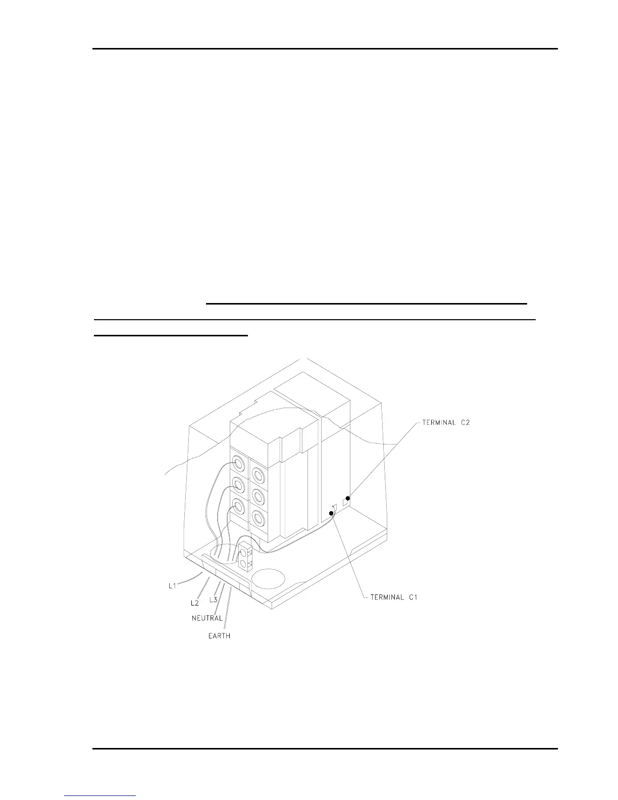
7.3.1 Ci 40 - 75 (Stop / start control)
All the mains supply leads connect to the compressor within the cover of the
combination pressure switch and starter. There is connection for 3 phases,
earth and neutral. Note: The neutral connection is made on the shunt
relay contact block (located inside pressure switch cover), at terminal
‘C1’ marked on the relay. Please refer to circuit diagram supplied with your
machine.
Note:- A No-Neutral option is available for your compressor. Please contact
Champion Compressor’s customer support department for assistance.
Fig. 1 - Electrical Connection Ci 75 (Stop / Start Control)