Champion Compressors Ltd. Manual No. 975203 Rev H
10
7.0 INSTALLATION AND PRE START CHECKS
WARNING: Incorrect Installation May Void Warranty.
Before installing your Champion Compressor check carefully for any transport
damage. Contact Champion Compressors immediately if any such damage is
found.
7.1 Location
The compressor cabinet as supplied is not weather-proof, and the compressor
should be installed inside (or in a sheltered location outside). The compressor
should be installed in such a way that the locations with respect to walls and
ceiling meet the requirements of the model general assembly diagrams.
(Refer Section 27).
The compressor must be placed on a flat surface and it must remain level at
all times. Packing shims should be used to level the compressor. The unit
must not be securely bolted down. When the need exists location pins should
be used.
IMPORTANT: Locate the compressor in an adequately ventilated area. Hot
air from the discharge duct must not recirculate to the air intake. Do not install
in an area where exhaust fumes from other equipment can be drawn into the
intake (or other toxic, noxious or corrosive fumes, chemicals or substances).
Where more than one compressor is installed in one location, not only must
proper care be taken with regard to access to each individual machine, but
special attention should be taken to ensure that there is no possibility of the
heated cooling air discharge from any one machine being directed into the
intake of another machine.
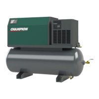
7.2 Connection To Air System
The compressor is supplied with either a 3/4” Gate valve (Ci 40/55) or 1” Gate
Valve (Ci 75/110) loose for installation into to ends of the compressor’s air
receiver. The connecting plant airline connection should be at least the size
of the prescribed gate valve, and if the pipe run is of any great length, the pipe
sizes should be increased by one size to minimise any pressure drop.
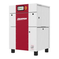
Note
: In base mount option configuration, the pressure switch is
supplied loose (on a 2m fly lead). This must
be fitted into the air supply
to provide a control signal for correct compressor operation.