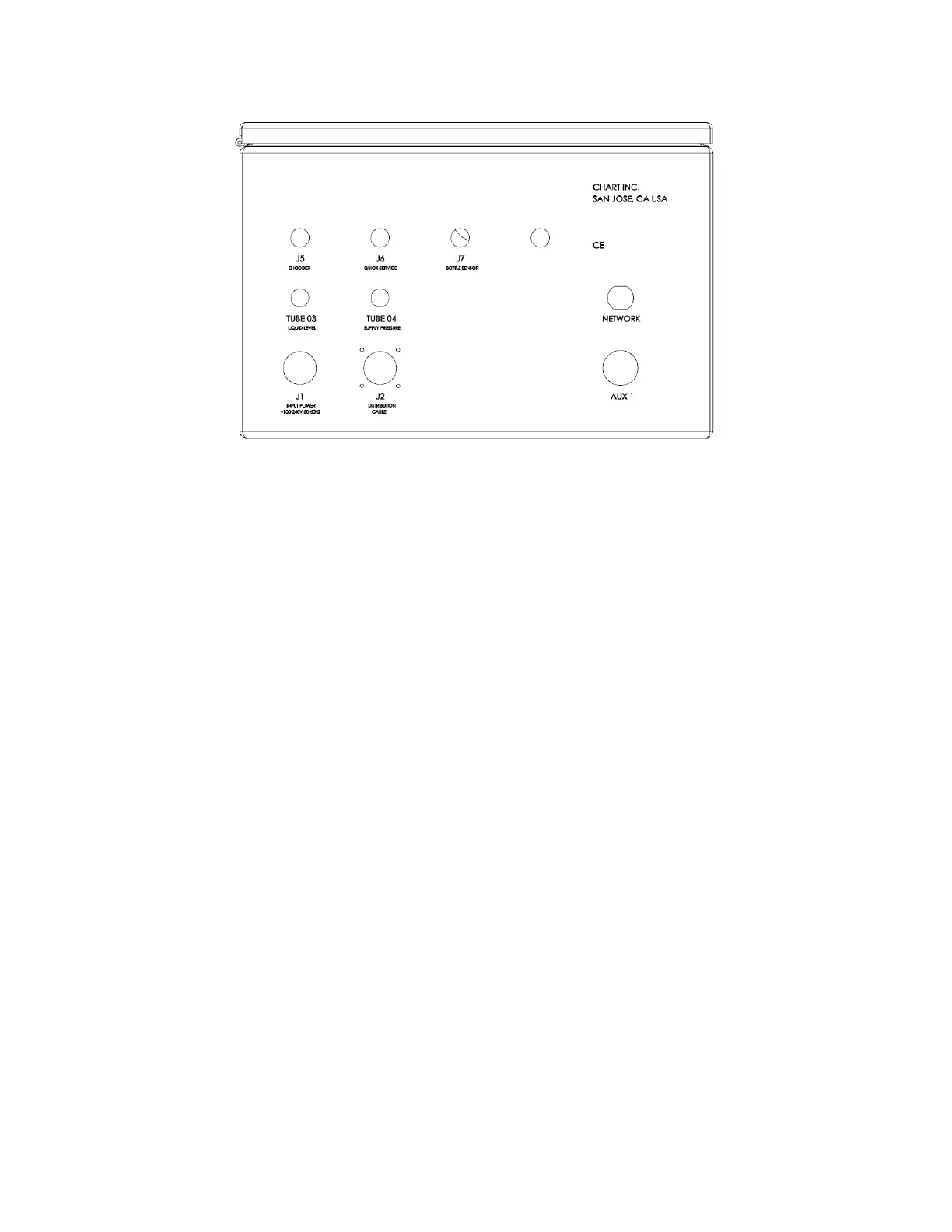
The bottom of the 2K controller is the electrical “hub”.
Input Power (J1)
The 2K controller power cable (6ft) is connected to the 2K controller at port J1.
Distribution Cable (J2)
The 2K controller I/O (input/output) cable, a component of the distribution block, is connected to the 2K
controller at port J2.
Tube 03
Tube 03 (UltraDoser Liquid Level) from the Gas Manifold Assembly is connected to the 2K controller at
Tube 03.
Tube 04
Tube 04 (UltraDoser Supply Pressure) from the Gas Manifold Assembly is connected to the 2K controller
at Tube 04.
Encoder (J5)
An encoder must be used to provide approximately 500 24v pulses per container. A PNP 12mm
proximity speed sensor is provided as a back up to provide the 2K controller with minimal pulses that are
used to calculate the line speed. The encoder (proximity sensor, if used) is connected to the 2K controller
at J5.
Quick Service (J-6)
The quick service solenoid valve located on the gas manifold assembly is connected to the 2K controller
at port J6.
Bottle Sensor (J-7)
A PNP bottle detect sensor connected to the 2K controller at port J7.
Network
An industrial Ethernet connection (8 pin M12) is provided to connect to the network for remote access to
the HMI display.