Installing the Encoder
The speed sensor is installed to detect filling line speed and must be installed for the UltraDoser 2K to
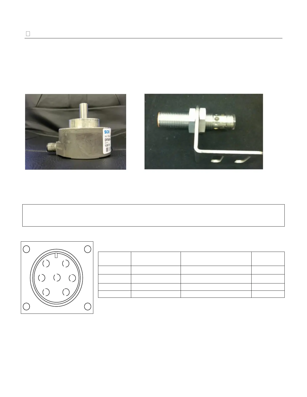
operate properly. Chart provides a PNP 12mm inductive proximity sensor (Image 5) with the UltraDoser
2K system. Chart highly recommends a SICK encoder (Image 4) be installed in lieu of a PNP sensor to
increase the resolution of the speed output for better performance of the UltraDoser 2K at higher line
speeds. The SICK encoder provided by Chart comes from the factory preset to 500 pulses per container.
See “Appendix A – Sensor Positioning” on page 63 for additional information.
Encoder Installation
IMPORTANT: Only one channel is used to provide necessary pulse for the UltraDoser 2K system. For
correct encoder functionality, shielded cabling must be used. The encoder should be grounded, either thru
the mounting bracket or separate ground wire.
Encoder Cable Connections:
* Wire color refers to the conductors of the shielded communication cable.
Image 5: 12mm Inductive Proximity Sensor