DF II Series User Manual 45
SPECIFYING THE CORRECT SENSOR
The single, most-common problem when measur-
ing load or torque is caused by the use of a sensor
that is not appropriate for the application.
Thesensorselectedshouldbespeciedsothat
the expected measured results occurs within the
20% to 90% capacity for the sensor. This is par-
ticularly important when using “full scale accuracy”
devices. Operating at too near either end of the
sensor’s capacity can lead to inaccurate measure-
ments, and worse, a damaged sensor.
The table below indicates the recommended sen-
sor capacities for different test applications.
UNDERSTANDING FULL SCALE CAPACITY
The SLC and STS Series sensors have accura-
cies based on “full scale”. The accuracy of these
sensors is based on the full scale capacity of the
sensor.
If the sensor capacity is 100 lbf, and the accuracy
is +0.25% of full scale, there will be more measure-
ment error effect at the lower end of the capacity.
In some instances, if too high a capacity sensor is
used, and the measurement is too near the zero
(under 10%), the measured results may indeed be
inaccurate, e.g. using a 100 lbf loadcell to measure
a 10 lbf load.
Expected Recommended
Load Capacity Model
50 - 225 gf 250 gf SLC-250G
500 gf - 1.8 lbf 2 lbf SLC-0002
2 - 9 lbf 10 lbf SLC-0010
10 - 22.5 lbf 25 lbf SLC-0025
10 - 45 lbf 50 lbf SLC-0050
20 - 90 lbf 100 lbf SLC-0100
40 - 180 lbf 200 lbf SLC-0200
100 - 450 lbf 500 lbf SLC-0500
200 - 900 lbf 1000 lbf SLC-1000
10 - 45 in-oz 3 in-lb STS-0003
2 - 10.8 in-lb 12 in-lb STS-0012
10 - 45 in-lb 50 in-lb STS-0050
20 - 90 in-lb 100 in-lb STS-0100
40 - 180 in-lb 200 in-lb STS-0200
Sensor Selection Guide
Load Min Max % Error
0 0 0.25 100%
2 1.75 2.25 25%
5 4.75 5.25 10%
10 9.75 10.25 5%
25 24.75 25.25 2%
50 49.75 50.25 1%
100 99.75 100.25 0.5%
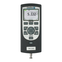
ACCURACY ERROR EFFECTS
Example: Assumes a 100 lbf (500N) load sensor with an
accuracy of +0.25% full scale.
100 lbf0 lbf
Example: The diagram shows the accuracy limits of a 100
lbf sensor with an accuracy specication of better than
0.25% full scale. The further the measured result from
capacity, the more error is introduced. The effects of
using an improper loadcell capacity on too low a measure
-
ment will increase the error in measured result.
Nominal