Assembly of Transmission
The procedures to assemble transmission are the
basically reverse to that of dismantlement. Pay
attention to the followings:
When mounting differential gear assy. onto clutch
housing, do not install the output flange first.
Mount the output shaft and put on the fore bearing
baffle of output shaft, put on fixing bolts and
tighten with 40Nm torque.
Mount the reverse gear idler and idler shaft onto
clutch housing.
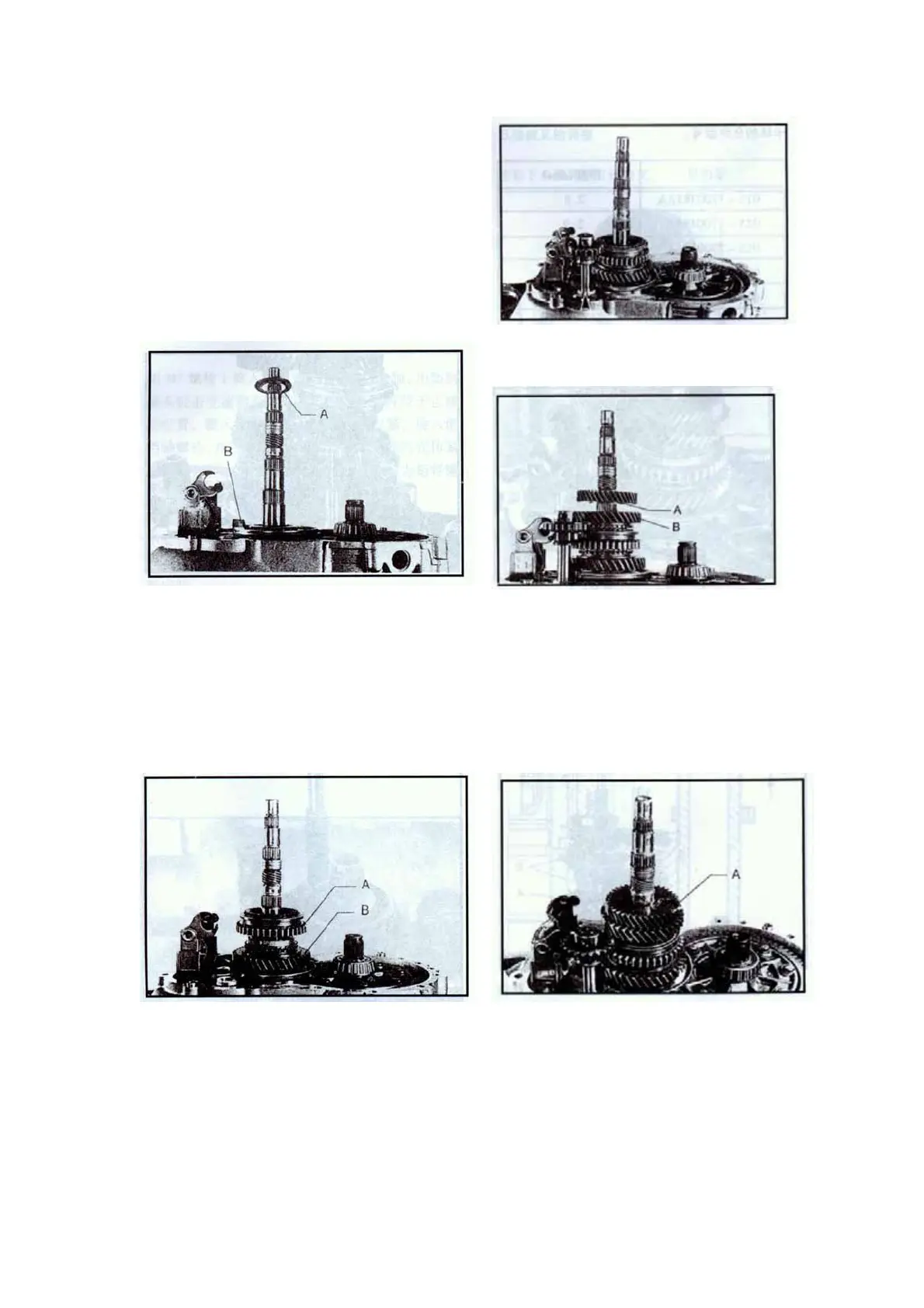
Put on the thrust plate and needle roller bearing.
Notice the direction of thrust plate, the inner
diameter of thrust plate A should well contacted
with bearing seat B.
When mounting gear-1 and gear-2 synch ring,
never confuse them; gear-1 synch ring is not moly
coated and has no teeth in three places.
Mount the needle roller bearings, synch rings
and gears of gear-2 and gear-3 driven gear.
When mounting gear-3 driven gear, the side with
dummy club should be toward the gear-2 driven
gear.
When mounting gear-1 and gear-2 synchronizers,
the side A with teeth should be toward gear-1
driven gear B.
After mounting gear-3 driven gear, adjust the
axial sizes with snap ring. When installing,
select the snap ring among the allowable types
that is the thickest and can be inserted into the
groove. When mounting snap ring, pay attention
not to expand it too much and ensure that it has
been installed into the groove.
14
 Loading...


