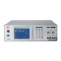
Electrical Safety Analyzer 19032-P Quick Start Guide
15
Display Area
Title List: This list displays the current setting of main unit or testing mode.
Function key message display area:
Under different display menus, there are different function
descriptions. The right side of display has corresponding
function keys. If the description is blank or gray scale font,
it means corresponding function is invalid.
Message Bar: This list indicates the setting method, the range of setting
value and the testing time.
Message Indication Diagram:
Remote: When this area is highlighted, it means the main unit is under
Remote status. That is the main unit controlled by PC through
RS232 or GPIB connect to PC. At the same time, all of keys are
malfunction except for [STOP] and [LOCAL] keys.
Lock: When this area is highlighted, it means the main unit is under setting
parameter-protected mode. Other keys are malfunction except for
“MEMORY”, ”TEST” and “KEY LOCK” modes.
Offset: When this area is highlighted, it means the main unit zeroed the
leakage current of test cable and test lead currently.
Error: When this area is highlighted, it means there is error message
produced.
Key Area
(1) Power Switch: The switch provides AC power source that the analyzer
is needed. Before starting, please read Chapter 3 “
Precaution before Use” firstly.
(2) STOP Key: Reset key, after pressing this key the main unit returns to
standby testing status immediately. That is cut output and
clear all of judgments simultaneously.
(3) START Key: After pressing this key, the main unit is under testing
status. The testing terminal has output and each
judgment function starts simultaneously.
(4) Function Keys: Function key. Under different display menus, there

 Loading...