Electrical Safety Analyzer 19032-P Quick Start Guide
35
RL8
1 2
RL2
1 2
RL3
1 2
RL4
1 2
RL5
1 2
RL6
1 2
DRIVE+
SENSE+
SENSE-SENSE-
DRIVE- DRIVE-
DRIVE+
SENSE+
RL1
HV1
HV2HV2
1 2
HV1
GB output
on front
panel
GB output
on rear
panel
RL7
1 2
1
High voltage
output on
rear panel
High voltage
output on
front panel
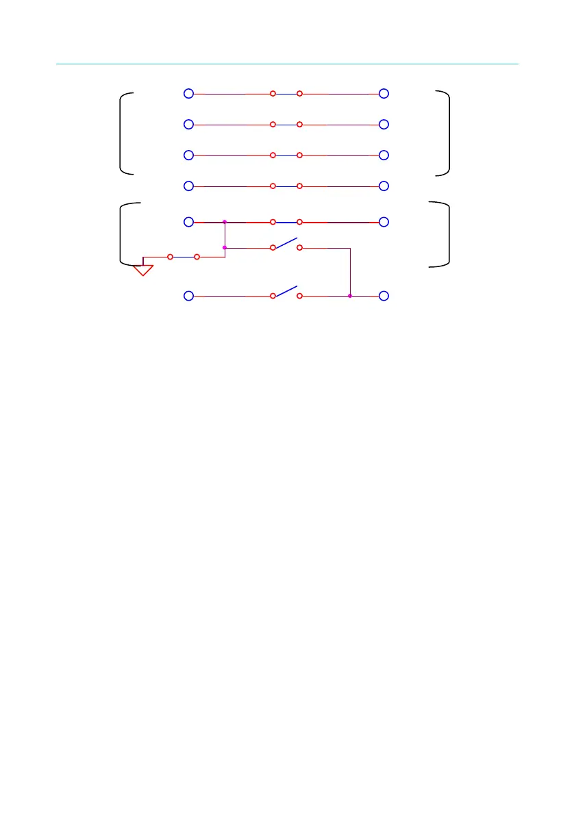
Figure 4-14
RELAY states:
RL1, RL2, RL3, RL4 = ON
RL5, RL8 = ON
RL6, RL7= OFF
4.8 Program Setting
4.8.1 Operation Method
1. When title shows “STEP SETTING”, press [U], [V] keys to move the
highlight cursor to the parameter item which want to set.
2. Press numeral/character keys or Function Keys to set this item
parameter data.
3. Press [ENTER] to confirm or press [CLR] to reset.
4.8.2 Various Parameter Settings
TEST STEP: It sets test step.
TEST MODE: Test mode selection. There are GB/AC/DC/IR/LC
(option)
/PA/OSC test modes can be selected. The following
describedparameter settings of various test modes.

 Loading...


