Electrical Safety Analyzer 19032-P Quick Start Guide
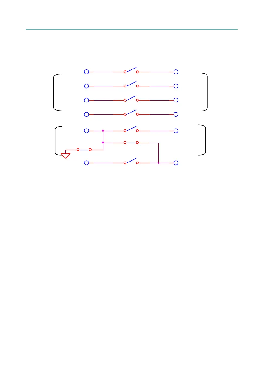
iii. When Channel 3 set to L and HV1 terminal on rear panel set to low
voltage terminal, connection diagram of front panel terminal and
rear panel terminal is as Figure 4-13 shown:
RL8
1 2
RL3
1 2
RL2
1 2
RL4
1 2
RL5
1 2
RL7
1 2
RL6
1 2
DRIVE+
SENSE+ SENSE+
SENSE-SENSE-
DRIVE-
HV2HV2
DRIVE-
DRIVE+
1
HV1HV1
RL1
1 2
High voltage
output on
rear panel
High voltage
output on
front panel
GB output
on front
panel
GB output
on rear
panel
Figure 4-13
RELAY states:
RL1, RL2, RL3, RL4 = OFF
RL5, RL7 = OFF
RL6, RL8 = ON
iv. When Channel 3 set to ¯ and HV1 terminal on rear panel set to
Floating, connection diagram of front panel terminal and rear panel
terminal is as Figure 4-14 shown:
34

 Loading...


